


A High-compression Combustion Head
Page 52
If you've noticed an error in this article please click here to report it so we can fix it.
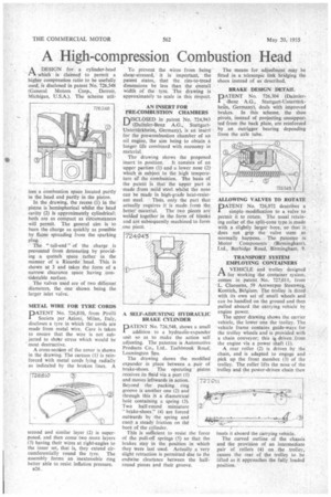
A DESIGN for a cylinder-head
which is claimed to permit a higher compression ratio to be usefully used, is disclosed in patent No. 726,348 (General Motors Corp., Detroit, Michigan, U.S.A.). The scheme util izes a combustion space located partly in the head and partly in the piston.
In the drawing, the recess (1) in the piston is hemispherical whilst the head cavity (2) is approximately cylindrical; both are as compact as circumstances will permit. The general aim is to burn the charge as quickly as possible by flame spreading from the sparking plug.
The "tail-end" of the charge is prevented from detonating by providing a quench space rather in the manner of a Ricardo head. This is shown at 3 and takes the form of a narrow clearance space having considerable surface.
The valves used are of two different diameters, the one shown being the larger inlet valve.
METAL WIRE FOR TYRE CORDS
DATENT No. 726,810, from Pirelli
Societa per Azioni, Milan, Italy, discloses a tyre in which the cords are made from metal wire. Care is taken to ensure that the wire is not subjected to she'ar stress which would be most destructive.
A cross-section of the cover is shown in the drawing. The carcass (1) is reinforced with metal cords lying radially as indicated by the broken lines. A second and similar layer (2) is superposed, and then come two more layers (3) having their wires at right-angles to the inner set, that is, they extend circumferentially round the tyre. The assembly forms an inextensible ring better able to resist inflation pressure.
826. To prevent the wires from being shear-stressed, it is important, the patent states, that the rim-to-tread dimensions be less than the overall width of the tyre. The drawing is approximately to scale in this respect.
AN INSERT FOR PRE-COMBUSTION CHAMBERS
nISCLOSED in patent No. 724,943
(Daimler-Benz A.G., StuttgartUnterffirkheim, Germany), is an insert for the pre-combustion chamber of an oil engine, the aim being to obtain a longer life combined with economy in material.
The drawing shows the proposed, insert in position. It consists of an upper portion (1) and a lower nose (2) which is subject to the high temperature of the combuition. The basis of the patent is that the upper part is • made from mild steel whilst the nose can be made in high-grade heat-resist ant steel. Thtls, only the part that actually requires it is made from the
bettermaterial. The two pieces are welded together in the form of blanks and are subsequently machined to form one piece.
A SELF-ADJUSTING HYDRAULIC BRAKE CYLINDER
PATENT No. 726,548, shows a small addition to a hydraulic-expander unit so as to make the action self adjusting. The patentee is Automotive Products Co., Ltd.. Tach brook Road, Leamington Spa.
The drawing shows the modified expander in place between a pair of brake-shoes. The operating piston receives its fluid via a port (1) and moves leftwards in action. Beyond the packing ring groove is another one (2) and through this is a diametrical hole containing a spring (3). Two half-round miniature " brake-shoes" (4) are forced outwards by the spring and exert a steady friction on thd bore of the cylinder.
This is sufficient to resist the force of the pull-off springs (5) so that the brakes stay in the position in which they were last used, Actually a very slight retraction is permitted due to the endwise clearance between the halfround pieces and their groove. 727011
The means for adjusfment may be fitted in a telescopic link bridging the shoes instead of as described.
BRAKE DESIGN DETAIL
PATENT No. 726,304 (Daimler-Benz A.G., Stuttgart-Untert(trkheim, Germany), deals with improved brakes. In this scheme, the shoe pivots, instead of projecting unsupported from the back plate, are reinforced by an outrigger bearing depending from the axle tube.
ALLOWING VALVES TO ROTATE
PATENT No. 726,972 describes a simple modification to a valve to permit it to rotate. The usual retaining collar of the split-cone type is made with a slightly larger bore, so that it does not grip the valve stem as normally happens. The patentee is Motor Components (Birmingham), Ltd., Burbidge Road, Birmingham, 9.
TRANSPORT SYSTEM EMPLOYING CONTAINERS
I-1 A VEHICLE and trolley designed
for working the container system, comes in patent No. 727,011, from L. Claessens, 59 Antwerpse Steenweg, Kontich, Belgium. The trolley is fitted with its own set of small wheels and can be handled on the ground and then pulled aboard the carrying vehicle by engine power.
The upper drawing shows the carrier vehicle, the lower one the trolley. The vehicle frame contains guide-ways for the trolley wheels and is provided with a chain conveyor; this i# driven from the engine via a power shaft (1).
A rear roller (2) is driven by the chain, and is adapted to engage and pick up the front member (3) of the trolley. The roller lifts the nose of the trolley and the power-driven chain then hauls it aboard the carrying vehicle.
The curved outline of the chassis and the provision of an intermediate pair of rollers (4) on the trolley, causes the rear of the trolley to be lifted as it approaches the fully loaded position.