


A SENTINEL BOILER IMPROVEMENT.
Page 30
If you've noticed an error in this article please click here to report it so we can fix it.
A Resume of Recently Published Patents.
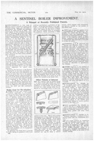
IMPROVEMENTS in that .type of
boiler which is familiar tomsers of the -Sentinel steam Wagon are described in apecification No. 213,682, the. patentees being. S. E. Alley and A. J. Hutt The main object of the iwienters has been that of increasing the grate area which is possible on a boiler of this type. The important difference as between this and former Sentinel-type boilers is in the formation of the outer shell, near its base, where, as may be seen on reference to one of the accompanying illustrations, it is bulged outwards: and is larger in diameter as compared with its size above. that point. The bulge is, as a matter of fact; on the same level as the fire, grate, and, the combustion chamber having a
• downwardly and outwardly flailing concal portion, exte»ding from a point immediately below the tubes to the fire • grate, allowSof the latter being considerably increased.
It should be observed that this design permits of additional-grate area being obtainable without increasing the diameter of the boiler itself, except locally at the situation of the bulge. There are two other advantages of this design, which; although peehaps secondary to the principal one described above, are yet 8uffieietitly important to merit some reference.
Increasing the diameter of the fire-box by flairing it, as has been described, reduces the water space and, therefore, the weight of water that has to be carried. The enlarged annular space provided at the level of the bulge permits of the collection of the scale and a deposit usually • to be expected at the bottom of the boiler. In addition, the form of the bulge employed affords additional flexibility to the boiler shell and makes provision for differencea of expansion as between the shell and the combustion chamber.
Brake Gear for Six-wheelers.
A FORM of brake gear which is par ticularly applicable to six-wheeled xehicles-or on other heavy-duty machines the weight of which calls for the provision of braking means more effective than is ordinarily necessary, is described
• in specification No. 213,665 by G. Page and another.. It embodies a form of tatchet gear which is operated by the
hand brake lever. The lever itself is plain and is mounted on a sleeve free, to revolve on a spindle which serves as a fulcrum. The brake transmission lever depends from a quadrant winch rides upon the sleeve already mentioned and upon the circumference of which ratchet teeth are formed. Other teeth of a similar nature are cut in the side of the quadrant. The hand lever is fitted.with the usual type bf'trigger and pawl. The latter engages with the teeth on the circumference of the quadrant, . and the bracket which supports the pawl is so formed as to embrace the top of the
• quadrant ; consequently; lateral move'inent of the hand lever will swing the quadrant sideways. The teeth on the side of the quadrant are in engagement with a fixed pawl.. .
In operation the hand lever is moyed forward, taking the. quadrant with it and making a preliminary application of the brake. If the first movement is not.stifficient to provide the necessary braking effort, the trigger on the lever is lifted and tile lever pulled back to re-engage the quadrant, which, .meantime, is held by the pawl at its side. A further movement of the hand lever increases the braking effect. To release. the brake the hand lever is moved laterally, disengaging the quadrant frOm the pawl at the side, and allowing it to move so as to release the tension in the brake rods.
Other Patents of Interest.
ON the ordinary type of leather-faced or fabric-faced cone clutch, on which the facing is secured by rivets, there is a • tendency, at high speeds, for the facing between the rivets, acting under the influence of centrifugal force, to leave the
surface of the cone. This is apt to make disengagement of the clutch at high engine speeds rather difficult. If too many rivets are used, the weight of the clutch centre is increased beyond what is desired. L. Renault describes, in specification No. 212,220, several methods of 6vereeming this •diffieulty; In most of them a wire or similar medium is used to bind the leather in place and supplement the rivets. In one, example the circumferential ,edges of.. the facing material are cut, to form 'a narrow tongue, which engages with .correspondMa grooves formed on the surface of the clutch cone.
A NEW. type of magneto appears to be
.foreshadowed by specification No. 213,871; -for which the M-L Magneto SyndiCate, Ltd., are responsible. The inventors are concerned with the arranges merits of the magnets, which, in their design, comprise a pair of parallel bars so magnetized that each has a free pole at or near its centre. .
ACCORDING to S. H. AttWood, and
Ruston and Hornsby, Ltd., a fault frequently met with in connection with force-feed lubrication systems has been that the lubricant under pressure is liable to be forced out of the filter chamber, so that it leaks away past the filler cap, causing, in some cases, entire loss of all the oil in the crankcase. As a remedy for that trouble these inventors enclose the end of the filter chamber in a socket provided with passages so arranged that any oil which escapes will flow back again into the crankcase. Their invention is described, in specification No. 213,646.
RATHER ingenious is the method of minimizing the chances of injury from a backfire when starting a vehicle by hand which is described in specification No. 213,739 by T. Noll. There are two springs coiled round the shaft of the starting handle and secured, at their outer ends, to the frame. Both are so wound that they allow the starting handle to revolve freely in the correct direction, but grip and hold it if it is reversed.
SPECIFICATION No. 213,859, by
W. E. Smith, deals with a collapsabre and portable.garage. It is constructed of tubular arches, of which there are three, two of them, the end 'ones, being of more substantial tubing. than the third. All the arches, as well as the cross-pieces and ridge pole, are designed to fold, and the arrangement of the hinges is such that, while one end arch folds so that the two parts touch one another, the others are designed to fold themselves. about it, the middle arch automatically. taking its conect position
relative to the other two. . .
FROM snecificalion No. 213,863 we gather that H. L. Sleigh and another• embed a metal strip in U-shaped rubber guides for frameless windows in order to stiffen those guides and keep them straight.
. .
SPECIFICATION No. 212,669, by W. Pickard, describes a' method of introducing steam with the combustible mixture.
OF two recent patents in connection
with the Fordson tractor,. one, No. 212,086; by W. L. Hill, suggests simple means Of equipping it with a transmission brake; the other, No. 212,333, by n. McKee Greasley, refers to a safety .gear, designed automatically to disengagia the clutch in the event of the tractor rearing.