


Valves Closed by Cams
Page 72
If you've noticed an error in this article please click here to report it so we can fix it.
A LTHOUGH spring-closed valves are C. used almost universally, progressive designers have always had positive twoway .operation in mind, the valve being cam-closed as well as cam-opened. A scheme of this -nature is disclosed in patent No. 809.027. (I. Suckling. 47
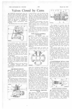
• Cashmere Road, Christchurch, New Zealand.) • The drawing shows the scheme applied to an overhead valve. The normal cam (1) moves a conventional rocker and pushes on the end of the valve stern;•this part of the design is standard practice.
By the side of the normal cam is a second one (2); this is a negative of the other, having a flat portion (3) opposite the lobe of the first Cam. A roller-ended rocker (4) transmits the thrust to the underside of a collar (5) on the valve stem; this is. screwed and forms a means for adjustment.
The closing action is not entirely positive, a spring loading being incorporated in case excessive strains might be set ttp., The spring is housed under the pillar (6) on Which the lower rocker is pivoted.
The design is said to ease the load on the camshaft, eliminate slack and resultant noise, and permit slow rotation a the valve.
DISC-BRAKE COOLING
PATENT No. 808,746 describes a scheme for cooling disc brakes. It is proposed to water-jacket the brake assemblies and include them in the conventional cooling system of the engine. (DaimlerBenz A.G., Stuttgart-Untertiirkheim, Germany.)
The drawing shows a half-section of a disc brake according to the invention. The innermost disc (.1) is the rotary member carrying facings of friction material.
It runs between a pair of cast-iron rings (2), one on the fixed face (3) and the other on a sliding member (4). The sliding member is an annular piston which, when the space (5) is pressurized hydraulically via the pipe (6), forces the assembly into braking contact.
The subject of the patent is the water jacketing as shown at 7. Water from the engine radiator enters the bottom and after circulating leaves via the top pipe connections.
An additional advantage of the scheme is that during it long descent the engine water may tend to cool off. It is prevented from doing so by the heat produced by the braking system.
WIDE-ANGLE UNIVERSAL COUPLING
PATENT No. 808.807 deals with universal joints for incorporation in the drive shafts of an independently sprung vehicle. The joint is of the Hooke type and uses rubber bushes. The bushes can withstand considerable deflection without adding undesirable stiffness to the suspension system. (Moulton Developments, Ltd., The Hall, Bradford-on-Avon. Wiltshire.)
A four-armed spider (1) forms the coupling member and each arm is pro vided with a bonded-on rubber bush (2). The arm is tapered and so is the bush, the large end outward in both cases. To the outside of the bush is bonded a metal shell (3) having a flared bore. The shell is split like a big-end bearing and the split is open when free. When the bolts (4) are tightened, the joint is closed and the rubber put under compression.
The distance between the bolt-holes of the forks is greater than the corresponding dimension between the holes in the spider; this ineans that the rubber sleeves have to be pulled outwards during assembly and so stress the rubber radially. This feature, coupled with the compression of the rubber, is said to lower the stiffness rate and so avoid alteration to the sus' pension under varying drive-shaft angles.
SELF-GOVERNING INJECTION PUMP A N injection pump for compressionti ignition engines is shown in patent No. 806,061. The chief novelty lies in the layout and action of the quantity regulating control. (Mono-Cam, Ltd., Oak Lane, London. N.2.) The plungers lie parallel with the spindle axis and a single cam works all of them in succession. The cam is shown at I and each plunger carries a mating roller (2), both being conical in outline.
To give quantitative control, each plunger works through a sleeve (3). The vertical position of this determines the point at which the spill ports are uncovered. All the control sleeves are held in a carrier disc (4) which is urged by a spring (5) into the full-fuel position.
The spilled fuel must first pass through an obstruction caused by a tapered needle (6). A pressure proportional to speed is built up in the chamber (7) which is separated from the lower space by a flexible diaphragm (8) and this pressure acts upon the carrier disc against its spring.
The tapered needle forms the main external control and is connected to the accelerator at the end (9). If set in any position, a drop in engine speed will cause the spill pressure to fall, causing the carrier disc to move in a direction corresponding to an increase in fuel.
The lever (10) is an excess-fuel device for starting; it allows the carrier disc to rise beyond the normal maximum position.
A DAMAGEPROOF SIGNAL LAMP T'RAFFICATORS which protrude from I. the side of a vehicle are liable to be damaged. A lamp fitting claimed to be able to resist impact is described in patent No. 808.627. (S. Bengtsson, Rattgatan 6, Langedrag, Sweden.)
A flange fitting (1) on the vehicle forms the anchorage, the lamp being shown at 2. The connection forms the subject of the patent; this consists of right-hand and left-hand coil springs (3) fitting tightly inside each other, with the whole assembly enclosed in a rubber tube (4).
SIMPLE IGNITION SYSTEM
AN ignition system requiring no makeand-break mechanism forms the subject of patent No. 808,714. A highfrequency oscillator, preferably using transistors, generates a high voltage which is fed direct to the sparking plugs via a distributor. The patentee is M. Guiot, II rue de la Neva. Paris.