L eyland Experimenting with Supercharging
Page 70

If you've noticed an error in this article please click here to report it so we can fix it.
ROAD vehicle engines should ideally give a constant torque irrespective of speed whereas in fact the real torque is usually much less at low engine speeds. A scheme for improving matters in this respect is disclosed in patent No. 685,841, by A. Mueller and Ley/41nd Motors, Ltd., Suffolk House, Laurence Pountney Hill, London, E.C.4.
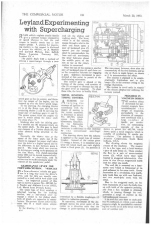
The patent deals with a method of driving a supercharger through a two-- speed gear so that its output, and therefore the output of the engine, can be stepped up over the lower speed range.
In the drawing, the charging blower (I) is of the Roots type and has two projecting shafts (2 and 3) carrying the usual pair of meshing gears (4 and 5). The power comes from the engine via gear 6, which drives the lower shaft via a free wheel (7).
Meshing also with the driving gear is a smaller one (8) mounted freely on the upper shaft. To this gear is fixed one element of a friction clutch (9), the other element being attached to the shaft.
Normally, the blower runs at the speed of the lower shaft, but if the clutch be engaged, the upper shaft takes over the drive at a higher speed, due to the difference in size between gears 6 and 8. The lower shaft can overrun its driving gear owing to the presence of, the free wheel. The clutch-operating collar (10) can be moved pneumatically. hydraulically or electrically, and its action can be made automatic under the control of the accelerator pedal.
GEARCHANGE LEVER FOR FORWARD-CONTROL VEHICLES
fN a forward-control vehicle the gear' box is a long way from the driver's lever, and the tvto are usually connected by a shaft which both slides and turns. An improved control of this type is shown in patent No. 685,940, by J. Naylor and Atkinson Lorries (1933), Ltd., Marsh Lane, Preston, Lancs.
The usual type of lever employs a spherical bearing for the rocking motion, and a ball-ended lever to engage a socket in the sliding shaft, both of which are expensive to manufacture. The present layout achieves the same end. In a much more simple manner.
In the drawing (I) is the 'gear lever a14
and (2) the sliding and rocking shaft. The lever, which is of flat section, passes through a slot in the shaft and bears upon a pair of hardened pins (3) spaced just far enough apart to accommodate the fore and aft movement; the lever fulcrums about the middle point of the slot so far as the rotary motion is concerned.
Near the top of the casing 's another pair of hardened pins (4) and these act as' the to-and-fro fulcrum for engaging a gear. Sideways movement is unrestricted at this point, to permit of the shaft-turning movement.
The control gate is placed at the bottom of the casing, and consists of ribs (5) arranged to obstruct the end of the gear lever as required To clear these ribs, the lever is bodily lifted.
NOVEL IGNITIONTIMING CONTROL
ASCHEME for varying the moment of ignition in accordance with the degree of suction in the intake manifold, is disclosed in patent No. 685,783, which comes from EtabbIissements Ducellier, 23, rue Alexandre Dumas, Paris. The variation is additional to that imposed
by t he conventional centrifugal mechanism.
The drawing shows how the scheme is applied to the usual type of contact breaker. Instead of the rocker pivot (1) being a fixture, it is mounted on a lever (2) which itself can rock slightly about a fixed pivot (3). Its position is
controlled by a flexible diaphragm (4) subject to induction pressure.
In operation, movement of the diaphragm moves the pivot point of the rocker in a direction such that the change in point-opening is negligible.
The movement, however, does alter the concentricity of the two contacts, and so one of them is made larger, as shown at 5, to accommodate the offset.
The scheme is claimed to be simple, practically frictionless and to give longer life to the contacts owing to the change of position.
The system is novel only in respect of the means adopted for utilizing the vacuum control.
PROGRESS IN MAGNETO DESIGN THE modern alloys developed for permanent magnets have revolutionized t h e design of magnetos, particularly • in the direction of compactness combined with a large number of sparks per revolution. An outstanding example of this is shown in patent No. 683,744, which shows quite a small magneto which is capable of producing 14 sparks per revolution. The patentee is Bendix Aviation Corporation, South Bend, Indiana, U.S.A.
The drawing shows the magnetic circuit of the machine. The magnet (t) is a bar type, and is held between a pair of pole shoes (2). These conduct the flux to a pair of seven-toothed rotors (2), which have their teeth located in staggered relationship. One rotor is thus always magnetized north and the other one south.
The coil (4) is mounted on a laminated core which is bifurcated at its ends adjacent to the rotor teeth. Every fourteenth of a revolution, two northpole teeth line up with one fork-end, and two south-pole teeth with the other.
Due to the staggered teeth, on the next fourteenth of a turn the forks line up with teeth of the opposite polarity, and thus a flux reversal is obtained which, in passing through the coil, generates a surge of current in the well-understood manner:
It is said that one shoe on each pole may be sufficient, in which event a dual magneto might be provided by connect' ing the second set of pole shoes with the core of another coil.


