


Patents Completed.
Page 24
If you've noticed an error in this article please click here to report it so we can fix it.
Complete specifications of the following patents will be sent to any address in the United Kingdom by the Sales Branch, Patent Office, Holborn, 1.V.C., upon receipt of eightperice per copy.
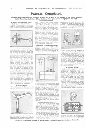
A Spring Transmission Gear.
J. V. Pletts, No. 676, dated 9th January, 1912.—This specification describes a system of transmitting power through a spring whereby energy may be accumu lated so as to be available when any special demand is made on the engine. The accompanying drawing shows one form in which it, may be applied to a motorvan. The engine shaft on the left drives a flywheel provided with a springcontrolled clutch which, by its centrifugal action when the speed rises, engages with the other clutch member which surrounds the flywheel. The drive is transmitted from this enter member through the gearbox and through a spring surrounding a free guiding shaft. When the engine is running slowly the clutch is not in engagement, but when it is speeded up the clutch is brought into engagement and winds up the spring until the power taken is sufficient to cause the engine to slow clown. 'The outer clutch member is held in this position by pawls and ratchet teeth on its outer edge, and the engine is free to accelerate again. If it, be accelerated sufficiently to engage the clutch again, more energy is stored in the spring until a drive is transmitted to the road wheels. So long as the load on t he engine continues above the normal, this cycle of action goes on repeatedly.
Motorbus Seats.
W. J. Lieu, and the London Coneral Omnibus Co., Ltd., No. 3209, dated 8th February, 1912.—A cushioning sup port is provided for a seat in a motorbus by mounting the seat on a plunger work ing in a cylinder. The cylinder is made practically airtight, and a non-return valve is fitted at the top to allow the admission of air but to prevent, so far as possible, its escape. A -liquid seal is provided at the bottom of the plunger to prevent the escape of air, and a stiff spring is also fitted in the bottom of the cylinder so that, when the seat is unloaded, it is lifted to its normal position and air is admitted to the cushioning cylinder. Should anything go wrong with the chock-valve at the top, the spring alone gives sufficient cushioning effect. A by-pass and non-return valve may be fitted at the bottom of the cylinder to return any of the liquid escaping to the chamber at the bottom.
A Pressure Lubricating System. Societe Anonyme de Zebra, No. 22,593/12, dated under International Convention, 11th October, 1911.—In this lubricating system a pump supplies air to a closed reservoir from which the oil
is fed through a number of sight. tubes in the ordinary way. A spring-controlled relief valve is fitted on to the reservoir, together with a needle valve which is capable of delicate adjustment. It is possible to make the lubrication proportional, to the speed of the engine by locking the safety valve, and by adjusting the leak through the needle valve to any desired amount. Increase of the engine speed then causes the air pressure to be raised proportionally, since the rate of leak is also proportional to the pressure, and a greater flow of oil is thereby obtained.
Keeping Stauffer Caps On.
A. Trio; No. 18,535, of 1912, dated under International Convention 25th August, 1911.—The object of this invention is to provide means for holding the caps of lubricators or tanks in place, when subjected to shocks or vibration, without interfering with the ease of putting the parts in place or removing them. As applied to a Stauffer lubricator, the neck of the fitting is provided with an internally-coned bush. The cap is provided with a central pin extending downwards into the interior of a tapered member which fits inside the coned bush. A. number of balls in radial slots are provided. These grip the central pin on the cap by their engagement with the coned bush, a spring forcing the coned member upwards to cause the balls to engage with the bush. The central pin is roughened by subjecting it when on the lathe to the action of a fine comb. It is inadvisable to turn the pin, for the helical groove thus provided enables it to work upwards although gripped by the balls. This locking device can be put out of action by pushing the cap right down and engaging a screwed per tion of the coned member with an inter.
'Hilly screwed part on the bush. cap can then be removed.
A Gearbox Brake.
Etablissements Lyonnais Roeliet Schneider, No. 22,369/12, dated under International Convention 21st December, 1911.—According to this invention a pair of gear wheels are provided irt the gearbox to act as an hydraulic brake. Their casing fits very closely round them except at two points which form the inlet and outlet respectively for fluid—usually oil—which is carried round by these two wheels. A passage is formed in the easing to provide the return channel for the circulating fluid, and a stop-cock on one end enables the flow of oil to be controlled. A very considerable braking effect is obtained by throttling this flow. By mounting one of the gearwheels on to the driving shaft, the brake is always available for action.