


PARCELS THICLE OF 1968
Page 51
Page 50
Page 52
Page 55
If you've noticed an error in this article please click here to report it so we can fix it.
WHEN considering the design of a parcel-delivery vehicle it is important to remember that in most cases the driver is working single-handed. He is responsible for delivering the goods and the safety of the load, in addition to his normal driving duties. He should, therefore, be the focal point of any such design and the vehicle must be easy not only to drive, but to unload.
This, of course, means that any such chassis must have a somewhat specialized specification and that massproduction vehicles do not lend themselves to ready adaptation, The principal objection is that normal-control chassis, whilst offering reasonably good cab access, are longer and less manoeuvrable than might be desired, whilst most forward-control vehicles do not provide easy access to the cab.
There are; however, exceptions among forward-control chassis. They are vehicles with underfloor engines, this being the only satisfactory way of ensuring a low and unobstructed cab floor line between the driving seat and the kerb-side entrance. Even those forward-control vehicles with the engine set well forward cannot have a low floor line at this point, because of the intrusion of the gearbox and propeller shaft, although there is a way out— albeit somewhat expensive—by employing front-wheel drive.
Small Vans for Cities
At this stage we should point out that we have in mind two distinct types of parcel-delivery vehicle. First, there is the van suitable for city work. Experience has shown that this should have a payload capacity of 2-3 tons and a body capacity of 500-600 Cuft. (11 ft. 6 in. by 6 ft. 9 in. by 6 ft. 6 in.). It is this type that is being considered in this article. The larger 5-6-ton van more usually employed on country deliveries does not present the same problems, although here, again, there is much room for improvement.
What are the requirements that dictate the design of a city-delivery parcel van? Manceuvrability is all-important, and for this reason the maximum overall length should. be no greater than 20 ft., and 17-18 ft. would be much more reasonable.
Overall length is not, of course, the sole deciding factor when considering manceuvrability. Much depends upon the wheelbase and steering lock if a small swept circle is to be obtained.
On the face of it, a chassis with a single front wheel possibly offers the greatest manceuvrability, but the vehicle under consideration will have an overall height of 10 ft. and the front-wheel loading might be as much as 2.tons. Thus, because a large-diameter wheel would be necessary. stability would be affected, and even were two small wheels to be spaced about 1 ft. apart to reduce the required diameter, the stability could not match that of a conventional four-wheeled layout, particularly on steeply zambered roads.
Minimum Gear Changing
Few vehicles are subjected to more concentrated stopping and starting than a parcel-delivery van, so it is in the interests of the driver and transmission that gear changing, and particularly declutching, should be cut to a minimum. Braking and steering must also be light.
All-round visibility is highly important, particularly when parking in congested streets, and this demands
generous glazing of the driving compartment. Unfortunately there does not seem to be a satisfactory alternative to rear-view mirrors to give visibility behind the van, other than the provision of large lights in the rear doors. These would have to be well reinforced to prevent accidental or deliberate breakage.
It is acknowledged by operators of this type of vehicle B16 that loading banks will continue in use for many years, and the generally accepted height for such banks is 3 ft. 6 in. Therefore, the loading height of the van should also be 3 ft. 6 in., and this figure could easily be obtained with present-day tyres without having to resort to wheel-boxes.
An oil engine is attractive for this type of vehicle, not only because of its fuel economy, but also because of longer life between major overhauls and more consistent operation. Even more important from the financial aspect, however, is a low chassis price. Unless a specialized chassis such as this can be offered for less than .£1,000, operators will put up with less suitable but less expensive standard layouts.
Within the broad framework of this specification it should not be difficult to offer such a vehicle this year, provided that it can be made suitable for other purposes, such as school buses and municipal appliances, and produced in relatively large numbers at a low price. In any event, a great number of standard production components would have to be employed.
As The Commercial Motor reported on May 2, Dennis Bros., Ltd., are, in fact, developing such a vehicle and a prototype is to be exhibited at theiComnnercial Motor Show this year.
TH
FTHE purpose of this article, however, is to look ahead I some 10 or 15 years, when a much wider choice of components and materials will be available
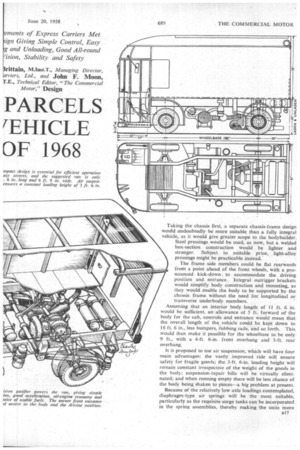
Taking the chassis first, a separate chassis-frame design would undoubtedly be more suitable than a fully integral vehicle, as it would give greater scope to the bodybuilder. Steel pressings would be used, as now, but a welded box-section construction would be lighter and stronger. Subject to suitable price, light-alloy pressings might be practicable instead.
The frame side members could be flat rearwards from a point ahead of the front wheels, with a pronounced kick-down to accommodate the driving position and. entrance. Integral outrigger brackets would simplify body construction and mounting, as they would enable the body to be supported by the chassis frame without the need for longitudinal or transverse underbody members.
Assuming that an interior body length of II ft. 6 in. would be sufficient, an allowance of 5 ft. forward of the body for the cab, controls and entrance would mean that the overall length of the vehicle could be kept down to 16 ft. 6 in., less bumpers, rubbing rails, and so forth. This would then make it possible for the wheelbase to be only 9 ft., with a 4-ft. 6-in, front overhang and 3-ft. rear overhang.
It is proposed to use air suspension, which will have four main advantages: the vastly improved ride will ensure safety for fragile goods; the 3-ft. 6-in. loading height will remain constant irrespective of the weight of the goods in the body; suspension-repair bills will be virtually eliminated; and when running empty there will be less chance of the body being shaken to pieces—a big problem at present.
Because of the relatively low axle loadings contemplated, diaphragm-type air springs will be the most suitable, particularly as the requisite surge tanks can be incorporated in the spring assemblies, thereby making the units more compact and reducing the amount of " plumbing " necessary.
As many designers are already discovering, the easiest way to apply air suspension to the front wheels of any commercial vehicle is to incorporate it in an independent suspension layout, using wishbones or a split axle beam. Independent front suspension will enable a full 450 wheel lock to be obtained, with ease, and this, because of the relatively short wheelbase of 9 ft., will make a turning circle of 34 ft. practicable, giving a swept circle of 40-ft. diameter, assuming a 4-ft. 6-in, front overhang. At the rear the wheels will be carried on triangulated trailing arms with the bellows behind the wheel centre line.
-Because some form of air compressor will be necessary to feed the suspension system, advantage can be taken of this to provide air braking, a simple air servo working a split hydraulic system. The obvious next step is to interlink the braking and suspension systems through the medium , of the front and rear levelling valves, so that the proportion of front-to-rear braking is adjusted automatically in direct relation to the front and rear axle loadings. Not only would this make the vehicle immeasurably safer to drive, but it would also reduce the tendency towards wheel locking and reduce tyre costs.
Simple Control So far as the engine and transmission are concerned, it has been agreed that an oil engine is desirable and that a simple form of transmission demanding little or no work from the driver is to be preferred, provided that it does not reduce the transmission efficiency too drastically. At present these features can be obtained with a small oil engine, preferably an air-cooled, horizontally opposed unit, working in conjunction with a torque converter with lock-up clutch, threeor four-speed automatic gearbox, or a conventional gearbox with a centrifugal clutch to give two-pedal control.
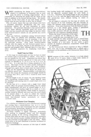
However, moving with (or ahead of) the times and looking at present developments, we think a free-piston engine working in conjunction with an axle-mounted turbine could do this job very much better and make the van as simple to drive as a steamer.
A relatively small free-piston gasifier developing 100 g.h.p. could be used with a simple transmission system and an inward-flow radial turbine with drooping torque characteristics. Assuming that the turbine would stand overspeeding to the extent of 45 per cent., this installation could be employed without a change-speed gearbox, but reduction and reverse gear trains would have to be provided. It might be possible to use reversible turbine nozzles, which could provide also a braking effect. The turbine speed would be in the region of 65,000 r.p.m.
Air-pressure Starting The gasifier could be used with a wide range of fuels, including all the grades of petrol, oil fuel, paraffin and lubricating oil. The main problem would be to start it, and the only satisfactory method of doing this is to employ dir pressure. This will entail a fairly large starting bottle containing air at a pressure of 600 psi., and this would be charged by an engine-driven compressor during normal service, although it would be advisable to provide means for exterior charging when the vehicle had been standing for some time.
Although at present the few gasifiers that are running are water-cooled, because extremely severe thermal loading conditions are encountered, air cooling is by no means impossible. If an air-cooled gasifier could be employed without the unit being too noisy. so much the better.
A gas bleed could be incorporated to drive a small turbine which, in turn, could power an electric generator and a cooling fan. Air would be drawn from the off side of the vehicle and ducted over the gasifier cylinders. Two small air compressors would be used—one for the starting bottle and one for the brakes and suspension—and these could be driven off the piston-synchronizing shaft, as could the gasifier lubrication pump. An electric pump would be supplied for the fuel lift.
As there need be no direct mechanical linkage between the gasifier and the turbine, the " transmission" layout would be greatly simplified, particularly as the relative positions of the gasifier and the turbine are not critical. The gasifier itself could be mounted in a cradle to allow ;t to be withdrawn sideways from the chassis for routine ,_ maintenance. Its main connections would be a flexible duct to the turbine, a fuel feed line, air lines for starting, electric wiring, and a linkage from the accelerator pedal.
The turbine itself would be carried directly on the rearaxle casing, together with the reduction and reverse gears, these driving straight into the bevel gear. No clutch would be incorporated in the transmission as the low pressure of the gasifier output when idling would not he sufficient to provide a drag on the turbine any greater than that associated with a conventional fluid coupling.
There is every reason to suppose that the design of freepiston gasifiers will have reached such a pitch in 10 years' time that they will operate with greater economy than existing oil engines. Being simpler in construction, they could be produced at a lower cost than an oil engine of equivalent power, besides having the advantage of weighing less. Further weight and cost advantages are endowed by the simple transmission, whilst the estimated life of a gasifier is about equal to that of an oil engine. Because the power turbine and its relevant gearing are unit-mounted with the rear-axle differential, the use of independent rear-wheel suspension is well worth consider ing. The mass of the drive assembly could then be supported by the chassis frame itself, the drive to the rear wheels being taken through open propeller shafts. This arrangementwould make it relatively simple to employ inboard-mounted disc brakes. These need not be large to give a good fade-free performance. The same size of unit as that being used in contemporary passenger cars would probably be sufficient. In the interest of standardization, therefore, it is logical that similar units should be used at the front. If necessary, a separate disc for the hand brake could be mounted behind the axle differential case, but it would simplify matters if the rear discs could be employed.
The wheels would have 6.000 or 6.50H semi-drop-centre rims carrying 7.50-16-in. tyres of the Michelin X type. The cool-running properties of such tyres make them perfectly able to cope with continuous running at more than 50 m.p.h. if necessary. These tyres could carry 271 cwt. each, making it possible to use four equally loaded tyres on the van.
Rather than employ a convention-al six-stud mounting for the wheels, a simpler method would be to carry them on. four dowels with a single large securing nut. This would also provide a cap end for the hubs and give a decorative effect. The use of such an arrangement would greatly simplify wheel removal.
Low Front-axle Load
As the van would be unlikely to run at more than 5+ tons gross weight, the front-axle loading would not be more than 21 tons and power-assisted steering would hardly be required, although this could be provided, if desired, using an air-pressure servo. The cheaper way would be to install a low-geared steering box and the steering wheel could carry a knob, as used on fork-lift trucks, tO allow the driver to turn the front wheels quickly from lock to lock when shunting.
A fairly upright steering column would be advantageous as, in conjunction with a driving seat with a tip-up cushion— something like a cinema seat—it would enable the van to be controlled from a standing position when the vehicle was to be driven for only a few yards between drops. The drag link could pass straight from the steering-box drop arm beneath the driver's seat to a frame-mounted relay linkage and thence to the steering arms. All the steering linkages would have self-lubricating bushes, thus eliminating greasing, as there would be no propeller shaft and the suspension points would be rubber-bushed.
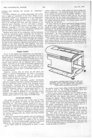
OME form of plastics material would obviously be used 01 for" the main body shell, and the body shape itself would take a simple box form. The floor could be of laminated plastics transverse planks for easy assembly and replacement. Because the main body sides need be only 11 ft. 6 in. long and 6 ft. 6 in. high, each side assembly could be made up in one piece, incorporating moulded-in pillars and, similarly, the roof could be a one-piece moulding.
• Plastics Body
This reduction in the number of parts would greatly simplify production and assembly. Body kits could be supplied to operators for them to assemble themselves. whilst separate items could easily be supplied for replacement. The mouldings could be offered in a range of several impregnated colours, thereby dispensing with the need for painting and giving a continuously new appearance which would be impervious to scratches.
Although in certain quarters there are doubts as to the wisdom of using completely transparent roof panels, because of the danger of heating the body interior in hot weather, there are no doubts about the amount of time that can be saved when loading and unloading by the extra light provided in the body.
An 11-ft. 6-in. by 5-ft. translucent panel in the roof would give ample light without too much heat penetration. whilst at the rear a translucent plastics roller shutter could he employed to let extra light into the back of the body. This would be used in conjunction with a laminated plastic tailboard and the translucent shutter might be of somi assistance to the driver when reversing.
The translucent roof panel would even let in a certait amount of-light at night if the van were parked in a well lighted street, but at least four roof lights would also halm to be provided. To assist depeot loading at night, 240v lamps could be arranged in the body, with a pull-out socke at the rear of the van to allow the interior to be illuminate( from the mains supply. The pull-out socket would auto. matically disconnect if the van were driven away withow the plug having been withdrawn.
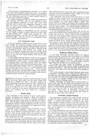
It is not contemplated that the driver will use the rear shutter and tailboard when making deliveries, as it naturally wastes time to do so. This is why careful consideration of the cab and forward body layout is most important. Assuming a cab length of 5 ft., it should be easy to provide a 3-ft.-wide doorway at the kerb side. The platform height should be about 14 in., which would require three risers, each of 9-jin., from the platform to the main body floor.
Intermediate steps between the platform and the floor could not be made full width because of the wheel-boxes. but as the overall vehicle width is 6 ft. 9 in. and 2 ft. is an ample width for each of the wheel-boxes, the steps could be 2 ft. 3 in. wide, located within the frame side members.
Bulkhead Behind Driver
A 2-f L-wide full-height partition would be required behind the driver to protect him in the event of a shifting load, but this would still leave a clear width of 4 ft. 9 in, between the body and the platform. This would be ample for large bulky parcels to be carried through: anything bigger than this is likely to be a two-man job.
No off-side cab door would be provided. A drop window with quick-acting winder would be incorporated alongside the driver. The near-side door would be of the jack-knife type lying across the near-side front glazing of the cab.
This would present a much wider doorway than would be possible if the door were to open in the plane of the cab side only, and would make it possible for the driver to leave through the front of the vehicle when drawn up close to a wall or to another vehicle on the near side, as frequently occurs at loading banks.
Another advantage of being able to unload from the front is that, once the rear shutter and tailboard have been shut after loading, they can be kept closed throughout the delivery round, thereby guarding against pilfering. The driver has only one door to lock each time he leaves the vehicle. Some form of electrically actuated lock operated by a switch close to the driving seat would be desirable for the shutter and tailboard.
, Protection Against Damage Two longitudinal rubbing rails at floor height would be provided to guard against minor damage to the body panels. A robust front bumper is important and large, rubber bumpers should be fitted at the rear corners,, also at floor height, to prevent damage when reversing into the bays. Flashing direction indicators at the front, rear and side will be fitted so as to be visible to all road users, including cyclists.
Two large external rear-view mirrors should be provided. The windscreen could be brought down almost to floor level and the jack-knife door section would be extensively glazed. .A single headlamp would. be sufficient and the near-side side lamp could be set in the front of the left-hand wheel-arch so that it shone forward through the door glazing and served to illuminate the step area. A powerful reversing light mounted beneath 'the floor to lessen the risk of accidental damage would be a standard fitting.