


A REMARKAi3LE Al IN STEAM WAGON TION.
Page 16
Page 17
Page 18
Page 19
If you've noticed an error in this article please click here to report it so we can fix it.
MANY STUDENTS of transport requirements consider that, if the steam wagon is to maintain its popularity amongst users of road vehicles, it will have to be considerably improved in order that it shall bear a closer relation
ship to petrol vehicle design. The average steam wagon of to-day is, more or less, a modification of the steam tractor, and it does not display to any marked degree that scientific distribution of material which is one of the causes of the success of the wagon using _petrol as its fuel. Why this should be it is somewhat difficult to understand, but possibly it is because the policy of the steam wagon builders in -the past has been that of "letting well alone." The steam wagon does its job, and usually does it well; but the discriminating buyer is beginning to ask for something less unwieldy, more silent, cleaner and easier to maintain than the types at present available. .
Last week, in an editorial dealing with the design of steam wagons, we referred to a-new -steam wagon
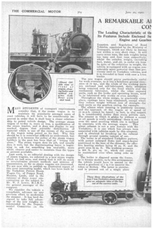
which we had seen, and stated that it will do much to revolutionize present methods and systems of transmission, so far as steam wagons are concerned. We are now able to publish an illustrated report of this most interesting model, which has been built by the Yorkshire Patent Steam • Wagon Co. of Pepper Road, Hunslet, Leeds, and is the
outcomeof three years' concentration on the subject by Mr. W. J. Lewin, M:I.M.E., the general manager of the company.
We consider the vehicle a remarkable advance on any previous effort to modernize the steamer. It has beeri designed to take full advan tage of the new weights recommended by the Departmental Committee on the 010 Taxation and Regulation of Road Vehicles, appointed by the Ministry of Transport, which are likely to become law within.a very short time. It will carry seven tons, the axle weights being ten tons and four tons respectively, whilst the unladen weight, excluding fuel, water, and ,oil, is under six tons. In pite of the reduction in weight, the vehicle is'equipped with an engine considerably more powerful than that previously used on Yorkshire vehicles,. and it is intended to haul with ease a 4-ton trailer.
The new wagon should prove particularly useful for work overseas, as it has a–minimum ground clearance of 14 ins., and the whole of the working parts are enclosed and self-lubricated, daily attention being required only for the front wheels and the mechanical lubricator, whilst the other exposed . parts, such as the brake and operating levers, need to he lubricated only weekly or even monthly.
Throughout the whole design, in practically every place, castings have been eliminated, except where they reduce weight without loss of strength—for . such parts as the gearbox easing, for example.
The silence when running is positively uncanny, and the approach of the wagon at a speed of 15 m.p.h. cannot be heard; in fact, in this respect it is considerably better than many private ears. The m'anner in which it glides by without a sound at all speeds is really astonishing: there is not even the usual snorting which one is inclined
to associate with the average wagon. This silent exhaust is not a new feature with the Yorkshire ; it is one which has always been, associated with vehicles made by this company, and is obtained by breaking up the exhaust through several nozzles instead of one.
The boiler is of standard Yorkshire pattern, with patent enlarged dome and super-heater positioned in the base of the chimney, the effective heating surface being 88 sq• ft. and the grate area 3+ sq. ft. The working pressure is 200 lb. per sq. in.' which can easily be maintained even' when using coke as fuel.
-The boiler is disposed across the frame, as in former models, as by this arrangement the vehicle would have to ascend or descend a gradient of 1 in 3 to uncover the tubes or firebox. The latter is circular, and is pressed out of a single plate with no welds. No engine parts or brackets connected with the motion work are fitted to the boiler, which is thus allowed complete freedom for expansion, whilst removal and replacement on the chassis are facilitated, as it is held in position by eight bolts only.
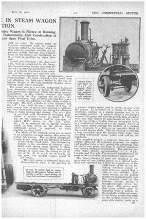
Rolled steel channels nag. deep and 3 ins_ wide are employed for the frame, the channels being turned outwards for the sake of securing accessibility. Accuracy as to frame alignment is not essential, as the engine and gearbox unit is three-point-suspended from exceptionally stout cross-members. No holes—beyond a few small ones for attaching the body—are drilled in the top or bottom flanges of the side-members, thereby maintaining their whole strength.
The power unit is a vertical,. compound, balanced type, somewhat similar in design to the well-tried type previously employed, which has given general satisfaction. In this vehicle, however, the engine develops over 50 i.h.p. against the 40 i.h.p. previously developed, and, as there are but few transmission losses, the efficiency of the whole vehicle is very high. The H.P. cylinder is 5 ins. diameter and the L.P.. 7 ins., both having a stroke of 8 ins. A neat, simple form of piston valve gearing is utilized, and very short ports ensure the maximum efficiency owing to rapid opening and closing. The valve gear
is provided. with Haekworth reversing gear, whilst a by-pass valve is fitted at the top of the cylinders, and is arranged to aamit H.P. steam to the L.P. cylin det. It is operated by a spring plunger, which is held down by the driver when additional power is required, as when starting on steep hills.
The whole of the working parts are enclosed in an accessible oil-tank casing, thus ensuring perfect lubrication. The balanced crankshaft Is only 20 ins, long, and the flywheel is bolted
to one of the crank webs. One interesting feature is the provision of circular cioss heads with spring rings similar to those on an ordinary pistol], these preventing leakage of water into the casing or of oil
out of it. At 10 m.p.h. to 12 m.p.h. on top gear, the normal engine speed is 380 r.p.m.
The feed pump is operated from the slowest-driven wheel in the gearbox at
a quarter engine speed, and is always in gear with the engine. It is bolted to a facing on the main crankcase casting in a simple manner and in an accessible position. A guide is fitted to the plunger between the pump kod and the gland, thus obviating wear and tear caused by side-thrusts on the latter. At the top of the cylinder, close to the by-pass valve, is a mechanical lubricator for the engine, driven at half engine speed through the medium of a rocking shaft, operated by a fork on an eccentric fitted to the second motion shaft. The oil delivery is through a boss provided upon the by-pass valve body, thus avoiding additional steam pints and making for simplicity.
The gearbox proper is spigoted into the engine easing ; thus, for all practical purposes, the engine and gearbox form a unit, giving the advantage that all shafts and gears are kept in perfect alignment and receive adequate lubrication. The gearing provides three speeds, corresponding to 3 m.p.h., 8 m.p.h. and 12 m.p.h. The material employed for the gears is 90-ton tensile, case-hardened forged steel.
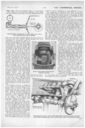
The three changes of gear are obtained by the move nent of one sliding pinion on a splined mainshaft and operated by a lever-in a quadrant at the right hand of the driver, following standard petrol vehicle practice, except that a gate is not utilized. Forward motion of the pinion meshes its internal teeth with the extended teeth of the primary pinion, giving a straight-through drive for top gear. The centre position gives middle gear by engaging with a pinion on ,k the layshaft, whilst movement , further pinion running freely on the mainshaft, but meshed with the third pinion on the second motion layshaft. The mainshaft spigot is supported in the primary pinion by a Hoffmann roller bearing. Behind the gearbox, in a separate oil-tight casing bolted to the latter' is a star-type universal joint with case-hardened steel bushes.
The propeller shaft is carried in a torque tube, the front end of which is provided with a spherical oil-tight joint, the cup of which is formed by the rear end of the universal joint cover. At its rear end the propeller shaft is carried in Hoffmann roller bearings of a in p 1 e propor Cons, and be tween these is situated a double ball-thrust 'bearing. A bevel and spur .doublereduction gear is embodied .in, the final drive.: .A dead axle is eMployed, and in 1,1 is the final drive and dif
ferential gearing are supported on Timken taper roller bearings of specially heavy design. The axle casing is a onepiece 40-ton steel forging of the pot type, the wheels
being mounted on bearings at its ends and driven through the medium of stout axle shafts, splined at each end and fitted into the central differential and the wheel driving caps respectively.
The main spur wheel of the final drive is bolted into position in the centre of the divided differential cage. The whole assembly of final drive and differential gearing can be lifted out after withdrawing the axle shafts, which can be removed after taking off the wheel driving caps. Everywhere, both in the axle and the engine-gearbox unit, the greatest care has been taken to prevent the . escape of lubricating oil, and from the appearance of the vehicle after some 500 miles' running it would seem that the measures taken have been completely successful.
A straight drop forging is used for the front axle, and the front springiaig is of an unusual type, cornprising two semi-elliptic springs jointed transversely at their rear ends by a third.
The front wheels are centrally pivoted. They are provided with plain phosphor-bronze bearings, and run on casehardened. drop forged stub axles.
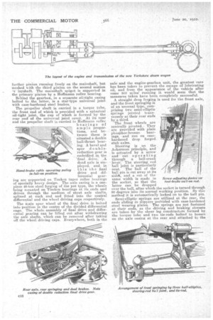
Steering is on the Ackerman principle, and is actuated by a screw and nut operating through a bell-crank ' lever. The steering rod ball joint is particularly • neat. The ball of the ball pin is cut away at its side*, and a cut of the
same. width is made in Screw-adjusting &vice tor the socket, so that the foot-brake nufl-on rod. hitter can be dropped
over the ball, after which the socket is turned through 90 degrees into its normal working position. By this method' it is automatically locked on to the ball pin.
Semi-elliptic springs are utilized at the rear, the ends Sliding in slippers provided with case-hardened
• steel wearing plates. The springs are not fastened at their ends, as the driving and braking stresses are taken lay the sheer leg construction formed by the torque tube and two tie-rods bolted to bosses On the axle casing at the rear and attached to the
side, and expanding against drums of large diameter bolted to the rear wheels. Much thought has been expended in designing these to obtain the maximum braking effect
without undue difficulty on the part of the driver. A very long pedal is provided for the foot brake, the adjustment for which is simple and accessible, whilst in the case of the hand brake the lever is provided with a pawl meshing with a toothed wheel at one end of the spindle of a small winding drum. At the front end of the shaft is a ratchet, so that the lever can be moved backwards and forwards, rotating the drum in one direction at each backward motion. A small trigger pedal provides a quick release for the drum, but, to prevent this unwinding too much of, the brake-actuating cable, one of the drum-spindle bearings is split, and can he closed on to the spindle by means of a setscrew, thus providing a braking effect. The hand brake toggle levers are connected together by a steel wire rope, which passes from one side, round two small pulleys fastened to a cross-member, anti, back to the lever on the other side. The steel wire rope from the winding drum ends in another pulley., round the rear of which passes the toggle lever cable, thus providing very powerful leverage.
View of final dri reduction torque tube, near the spherical joint; at the front. The brakes are particularly efficient, both hand and foot -brakes operating on shoes situated side by
The bunker capacity is sufficient For a day's run, and there is no reason w'hy a vehicle of this type should -not be put on 80 to 90 miles' daily service, because, when fully loaded, average speeds of 14 m.p.h. to 16 m.p.h. can easily be obtained. The capacity of the water tank is sufficient for 20 to 30 miles. It is fitted with strainers, steam water lifter, suction pipe, and 30 ft. of hose.
Very excellent fuel and water consumption figures -have been obtained, and, although -we are not at present permitted to disclose these, we may mention that they have even exceeded expectations, whilst the wagon has taken on top gear hills which were quite beyond the capacity of the previous model.
e have not yet referred to one very important feature in the construction, and that is its remarkable accessibility and the ease with which it can be assembled or dismantled for repair.
The wheelbase is identical with that of the previous model, and the level of the top of the chassis is 3 ft., whilst the whole design is arranged so that the various types of standard bodies already in use can -be utilized on. the new machine.
A striking proof of the efficiency and free-running of the transmission and engine was given to us when one of the rear wheels was jacked-up clear of the ground, the gear put into top-speed position, the cylinder cocks opened, and the free rear wheel spun round by one man so that it drove the engine. It should be pointed out that in doing this the differential also came into action and doubled the normal gear ratio, thus inereasiog the actual effort required.
The engine and transmission have been tested in the chaisis with the engine running at something like 1,400 -revolutions per minute, by jacking up the rear wheels and running the engine in gear. On one occasion, white doing this, the vehicle Jumped the jacks, but it was stopped within a few feet, by means of the foot brake, thus giving proof
of the power that Can be exerted ry the latter. During the trial trip made with the wagon, we particularly noticed
its ease of control. The driver twisted it round in narrow places as if it *ere merely a taxicab, the centrally pivoted front wheels.giving remarkably easy steering, which is assisted by the large lock, whilst the inclination of the steering pillar makes this more comfortable for the driver. The steering wheel is provided with a -handle, and can be operated very
rapidly. The braking was also shown to be exceptionally powerful, either brake being sufficient to hold the vehicle on any hill.
. Patents have either been ohatined, or have been applied for, for all the main features of the b oil e r, engine, transmission, brakes, and pump.
We have already referred to the matter of accessibility, but it may also to mention the fact that with pit is required.