


PATENTS SUMMARIZED.
Page 22
If you've noticed an error in this article please click here to report it so we can fix it.
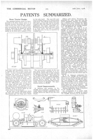
Boon Tractor Design.
The patented features which are incorporated in the Boon tractor seem to be directed towards increasing the accessibility of the main units of that tractor ; also, and perhaps this is a natural cora Lary; to improving its design as regards simplicity of construction, The chassis carries at its front end a radiator of the tank type, and immediately behind this is situated the four-cyl'nder engine and clutch. A short universally-jointed shaft transmits the power to a bevel-driven gearbox carried immediately behind, instead of in front of the rear axle. . The construction of the box is clearly shown by the drawing which we reproduce from the patent specification. It will he noted that the differential case carries three spur rings, and into these, by sliding in the usual manner, are engaged one or other of three corresponding gears on the layshaft, which is driven direct by the crown wheel of the bevel pair.
At the ends of the differential shafts are spur gear pinions and brake drums. The pinions gear into large spur wheels on the axle itself. The near side spur wheel is bolted direct to.its corresponding road wheel. The off-side wheel, however, runs free upon the axle, but is normally coupled to the road wheel by means of a substantial but easily removable pin. Mounted upon the boss of the spur wheel is a winch drum, and this is coupled to the spur gear, or not, as required, by a similar pin.
The arrangement permits of the rear axle being sprung, provided it is constrained by radius rods to keep constant the distance between its centre and that of the differential shaft. The position of the gearbox renders it readily accessible, and owing to the position of the main driving pinions behind the axle, the torque reaction on the axle itself is downwards, instead of upwards. The epecification number is 115,269.
Detail Improvements.
E. Williams and another, in No. 115,328, have patented a construction of motor balance plough embodying independent drives for each of the two road wheels. Alldays and Onions Pneumatic Engineering Go., Ltd., have now had the patent completed whereby, by interposing a distance piece between the frame member and the axle member, the effect of the springing may be entirely neutralized. Specification No. 115,398.
Leyland Motors, Ltd., and J. G. P. Thomas, have devised, as related in No. 115,397, an ingenious change-speed-gear, which is operated by engine suction. A camshaft, which is presumably to be carried within the gearbox, and at the end of which is a bevel wheel, by its rotation prearranges the change-speed levers, forks, ete., within the gearbox. The bevel wheel at the end of the camshaft gears with another at the lower end of a vortical shaft at the top of which is secured the change speed lever. The latter works in a slotted quadrant. It is, moreover, extended, and the opposite end of the lever to that at which the handle is farmed is disposed in the loom of a flat, plate. Underneath the flat plate is a small plunger, the depression of which puts the engine induction pipe in corninunieation with the gear operating cylinder. When, therefore, the change. speed lever is lifted from the ratchet so as to free it for movement to another notch, depression of the small plunger takes place, so that the piston within the pneumatic cylinder, acting under the influence of engine suction, moves to effect the change of gear. The operations performed by the change-speed lever are, therefore, dual. Lifting it allows the suction to operate the actual changespeed gear mechanisms : turning it about, its axle revolves the cylinder camshaft and insures that the correct gear is engaged.
In F. D. 'Walton's carburetter, described in No. 115,283, the fuel enlarges into a narrow annular opening, and air 1.9 drawn at high speed through this opening, thus mixing the fuel. The annular opening surrounds a hollow double-ended cone which is kept hot by means of ex
haust gases fed into its interior. By movement of this double-ended cone, the width of the opening may be adjusted. Another carburetter design is described in No. 115,262, by E. Dobson._ An arrangement of a motor roadsweeping machine is covered by patent No. 115,246. Patentee, W. II. Serottorn.