


Patents Completed.
Page 30
If you've noticed an error in this article please click here to report it so we can fix it.
LUBRICATOR.—Austin Motor Co., Ltd., and Another.—No. 15,866, :dated 13th July, 1906. D indicates a set of three rotary pumps having a common axis, The middle pump draws oil from the receiver (B) through a pipe (d) and delivers it through a pipe (d1) to the middle bearing (E) of the crankshafts, and through the two branch pipes (d2) of the bearings (El). The two outside pumps have, together, a greater capacity than that of the middle pump, and each of them, respectively, draws oil through a pipe (e) from the bottom of the compartment (A) of the engine case, and delivers the same through an outlet (f) into the receiver (B). These two pumps ensure a rapid drainage of the engine case and prevent the return of oil from the receiver into the case (A).
TIRES FOR HEAVY VEHICLES.— Affleck.—No. 17,604, dated 4th August, 1906.—The rim (A) of the wheel (B) is
formed, at one side, with a fixed flange (C), whilst, at the opposite side, is a detachable flange (D) of similar form, secured to the rim by bolts (d) passing from side to side. At the middle of the rim is a loose metal ring (G) of wedge shape in cross section. This ring, with the two flanges, forms dove-tail channels in which are placed small square wooden blocks (E) cut with the grain and inserted in the rim while the flange (D) is loose. After the blocks are inserted, the flange (D) is screwed up and binds the blocks in the dove-tail channels. To pro
vide increased pressure, and to form the wooden blocks into a solid mass, webbed wedges (F) are driven in between the blocks, and these compress the blocks in all directions so that the face of the tire is hardened and the wearing surface is strengthened.
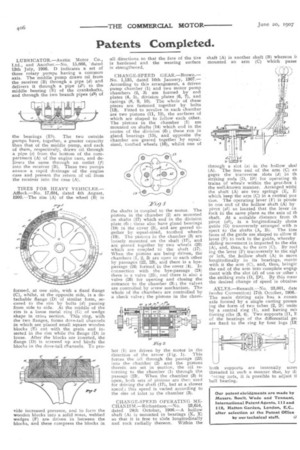
CHANGE-SPEED GEAR.—Brown.No. 1,135, dated 16th January, 1907.— According to this arrangement, a driven pump chamber (1) and two motor pump chambers (2, 3) are formed by end plates (4, 5), division plates (6, 7), and casings (8, 9, 10). The whole of these pieces are fastened together by bolts (13). Fitted to revolve in each chamber are two pistons (11, 12), the surfaces of which are shaped to follow each other. The pistons in the chamber (1) are mounted on shafts (14) which end in the centre of the division (6); these run in gland bearings (15), and opposite the chamber are geared together by equalsized, toothed wheels (16), whilst one of the shafts is coupled to the motor. The pistons in the chamber (2) are mounted on shafts (17) which end in the division plate (6)) these also have gland bearings (18) in the cover (5), and are geared together by equal-sized, toothed wheels (19). The pistons in the chamber (3) are loosely mounted on the shaft (17), and are geared together by two wheels (20) which are coupled to the shaft (17). When the pistons are being driven, the chambers (1, 2, 3) are open to each other by passages (22, 23), and there is a byepassage (24) formed in the cover (4). In connection with the bye-passage (24) there is a valve (25), and there is also a valve (26) for opening and closing the entrance to the chamber (3); the valves are controlled by screw mechanism. The whole of the chambers are controlled by a check valve; the pistons in the cham her (1) are driven by the motor in the direction of the arrow (Fig. 1). This forces the oil through the passage () into the chamber (2) and the pistons therein are set in motion, the oil returning to the chamber (1) through the passage (23). When the chamber (3) is open, both sets of pinions are then used for driving the shaft (17), but at a slower speed; this speed is varied according to the size of inlet to the chamber (3).
CHANGE-SPEED OPERATING MECHANISM.—Richardson.—No. 23,654, dated 24th October, I906.—A hollow shaft (A) is mounted in bearings (X, X) so that it is free to slide longitudinally and rock radially thereon. Within the shaft (A) mounted is another shaft (B) whereon it an arm (C) which passe
through a slot (a) in the hollow shaf (A). The free end of the arm (C) en gages the transverse slots (d) in th striking rods (D, D1) for operating th trains of wheels within the gear-box i the well-known manner. Arranged withi the shaft (A) are two springs (E, E: which keep the arm (C) in a central pus: tion. The operating lever (F) is pivote to one end of the hollow shaft (A) by pivot (al) so located that the lever ca rock in the same plane as the axis of th shaft. At a suitable distance from th pivot (al), is a longitudinally slotte guide (G) transversely arranged with n spect to the shafts (A, B). The Min faces of the guide are shaped to allow th lever (F) to rock in the guide, whereby sliding movement is imparted to the sha (A), and, thus, to the arm (C). By rodl big the lever (F) transversely to the rigl or left, the hollow shaft (A) is move longitudinally in its bearings, movin with it the arm (C), and, thus, bringir the end of the arm into complete engagi merit with the slot (d) of one or other the striking rods (D, D1). By this meat the desired change of speed is obtaine( AXLES.—Renault.--No. 23,001, date (under Convention) 17th October, 1906.The main driving axle has a count( axle formed by a single casting presen big the form of two tubes (2, 21) unite by a central ring (1), and having reii forcing ribs (3, 4). Two supports (11, 1: of the bearings of the differential get are fixed to the ring by four lugs (131
both supports are internally scree threaded in such a manner that, by di 'acing nuts, it is possible to adjust ti ball bearing.