


SIX-WHE BUSES IN SERVICE.
Page 16
Page 17
Page 18
Page 19
If you've noticed an error in this article please click here to report it so we can fix it.
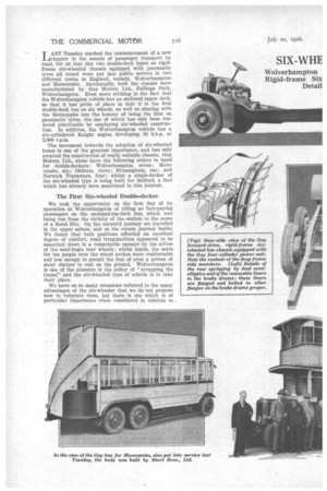
TAST Tuesday marked the commencement of a-new J chapter in the annals of passenger transport by road, for on that day two double-deck buses on rigidframe six-wheeled chassis equipped with pneumatic tyres all round were put into public service in two different towns in England, namely, Wolverhampton and Morecambe. Incidentally, both the chassis were manufactured by Guy Motors, Ltd., Fallings Park, Wolverhampton. Even more striking is the fact that the Wolverhampton vehicle has an enclosed upper deck, so that it has pride of place in that it is the first double-deck bus on six wheels, as well as sharing with the Morecambe bus the honour of being the first on pneumatic tkres, the use of which has only been rendered practicable by employing six-wheeled construction. In addition, the Wolverhampton vehicle has a six-cylindered Knight engine developing 76 b.h.p. at 2,000 r.p.m.
The movement towards the adoption of six-wheeled buses is one of the greatest importance, and has only awaited the construction of really suitable chassis. Guy Motors, Ltd. alone have the following orders in hand for double-deckers: Wolverhampton, seven; Morecambe, six; Oldham, three; Birmingham, one; and Norwich Tramways, four; whilst a single-decker of the six-wheeled type is being built for Salford, a fact which has already been mentioned in this journal.
The First Six-wheeled Double-decker.
We took the opportunity on the first clay of its operation at Wolverhampton of riding as fare-paying passengers on the enclosed-top-deck bus, which was being run from the vicinity of the station to the scene of a floral fête. On the outward journey we travelled in the upper saloon, and on the return journey inside. We found that both positions afforded an excellent degree of comfort, road irregularities appeared to be smoothed down in a remarkable manner by the action of the-semi-bogie rear wheels; whilst inside, the seats for ten people over the wheel arches were comfortable and low enough to permit the feet of even a person of short stature to rest on the ground. Wolverhampton Is one of the pioneers in the policy of "scrapping the trams;" and the six-wheeled type of vehicle is to take their place.
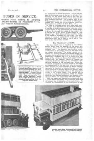
We have on so many occasions referred to the many advantages of the six-wheeler that we do not propose now to reiterate them, but there is one which is of particular importance when considered in relation to the employment of double-deck buses. This is the fact that, in the unusual event of the tyre on a bogie wheel deflating, the bus would lean over to only half the amount by which that particular wheel drops, the list thus beconfing negligible. The 57-seater body' on the Wolverhampton bus was constructed by Christopher Dodson, Ltd., whilst that on the 53-seater vehicle for Morecambe is a product of Short Bros., Ltd.
In view of criticisms which have been made upon the weight of six-wheelers, it is of interest to note that, in the case of the Morecambe vehicle, which has a fourcylinder engine of Guy manufacture, the chassis weight is 3 tons 4 cwt., and the weight of the complete bus 4 tons 14 cwt. 2 qrs., giving a body weight of I ton 10 cwt. 2 qrs. With the six-cylinder model the weight of the chassis is increased to 3 tons 7 cwt. The latter chassis, of course, is equipped with larger tyres, these being 36 ins. by 8 ins., in place of the 34 ins. by 7 ins. used on the four-cylinder chassis.
Bus Chassis now Available.
The bus chassis can be supplied in two distinct models, apart from the question of the power unit employed. These two are the forward type and the ordinary type. The forward type involves certain modifications in the design, which we will refer to in our chassis description. The actual chassis we examined was the four-cylinder forward-dash model with an engine having a bore and stroke of 4/ ins. and 51 ins. respectively, developing 38 b.h.p. at 1,000 r.p.m. and being of the well-known Guy patent design which is claimed—and, we consider, rightly—to possess the simplicity of the side type with the advantages, such as extra efficiency, of the overhead type. In the forward-dash model all the important details of the engine are concentrated at the near side with the exception of the magneto, the contact breaker of which, however, can easily be examined or adjusted through a porthole in the partition at the near side of the driver's cabin, whilst the large detachable plate at this point gives access to the cylinder heads. The steering box is mounted over the front dumb-iron, whilst the changespeed gate and the hand-brake lever are situated within the main frame and arranged for left-hand control.
Both the engine and the gearbox are mounted upon a patent flexible sub-frame, which insulates them from all stresses due to distortion of the main frame. In addition, by disconnecting at the three points of sus pension, the sub-frame complete with its units can be Supported by jacks and the main frame lifted over it.
The result of this construction has involved the devising of a special means for the connection between the change-speed gate and the gearbox. This takes the form of a tube which can both slide and rotate, this tube being given universal action by being mounted in spherical bearings, the rear bearing being carried on the sub-frame and so arranged that the tube can Slide through it.
The selector lever is carried on the tube by fine serrations and is locked bY nuts, the serrations and nuts thus affording adjustment in two directions. Allowance for movement is also permitted in the petrol and oil piping, which are provided for this purpose with inserts of Petro-FIex tubing; this also applies to• the pipe leading from the inlet manifold to the Autovac.
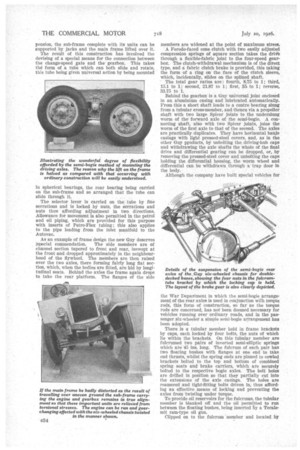
As an example of frame design the new Guy deserves [special commendation. The side members are of channel section tapered to front and rear, inswept at the front and dropped approximately in the neighbourhood of the flywheel. The members are then raised over the two axles, there forming fairly long fiat section, which, when the bodies are fitted, are hid by longitudinal seats. Behind the axles the frame again drops to take the rear platform. The flanges of the side
members are widened at the point Of maximum stress.
A Ferodo-faced cone clutch with two easily adjusted compression springs of square section takes the drivle through a flexible-fabric joint to the four-speed gearbox. The clutch-withdrawal mechanism is of the direct type, and a fabric clutch brake is provided, this taking the form of a ring on the face of the clutch sleeve, which, incidentally, slides on the splined shaft,
' The total gear ratios are fourth, 8.75 to 1; third, 15.1 to 1; second, 21.87 to 1; first, 35. to 1; reverse, 33.75 to 1.
Behind the gearbox is a Guy universal joint enclosed in an aluminium casing and lubricated automatically. From this a short shaft leads to a centre bearing slung from a tubular cross-member, and thence via a propeller shaft with two large Spicer joints to the underslung worm of the forward axle of the semi-bogie. A connecting shaft, also with two Spicer joints, joins the worm of the first axle to that of the second. The axles are practically duplicates. They have horizontal banjo casings with light pressed-steel covers, and, as in the other Guy products, by unbolting the driving-hub caps and withdrawing the axle shafts the whole of the final drive and differential gearing can be dropped, or, by removing the pressed-steel cover and unbolting the caps holding the differential housing, the worm wheel and differential can be withdrawn through a trap door in the body.
Although the company have built special vehicles for the War Department in which the semi-bogie arrangement of the rear axles is used in conjunction with torque rods, this form of construction, so far as the torque rods are concerned, has not been deemed necessary for vehicles running over ordinary roads, and in the passenger six-wheeler a simple semi-bogie arrangement has been adopted.
There is a tubular member held in frame brackets by caps, each locked by four bolts, the nuts of which lie within the brackets. On this tubular member are fulcrumed two pairs of inverted semi-elliptic springs which are 45 ins. long. The fulcrum of each pair has two floating bushes with flanges at one end to take end thrusts, whilst the spring ends are pinned to cowled brackets bolted to the top and bottom of combined spring seats and brake carriers, which are securely bolted to the respective bogie axles. The bolt holes are drilled in position so that they partially cut into the extensions of the axle casings. The holes are reamered and tight-fitting bolts driven in, thus affording an effective means of locking and preventing the axles from twisting under torque.
To provide oil reservoirs for the fulcrums, the tubular member is blanked off and the oil permitted to run between the floating bushes, being inserted by a Tecalemit ram-type oil gun.
Clipped on to the fulcrum member and located by
dowels are brackets for carrying the brake connections. This brake gear has had to be most carefully designed to give equal braking under all conditions of loading and axle movement, so that there is no risk of the brakes freeing themselves automatically. All the brake drums are provided with renewable liners with flanges bolted to others on the brake drums proper. The hand brake acts on the drums of the forward bogie axle, and the foot brake on those of the second driving axle, but, of course, both brakes act on all four wheels through the medium of the final-drive gearing.
Drain pipes are provided to lead any surplus oil clear of the brake drums, whilst covers prevent the entry of dirt and water.
In some six-wheelers of the semi-bogie type trouble has been experienced through loosening of the fulcrumbearer brackets at their point of attachment to the frame. This matter has received careful consideration in the Guy, and each of the two brackets has a large area of contact with the frame and is secured by 10 well-fitted bolts, these being both in the lower flange of the frame and in the web.
The drive is taken through the springs, the plates of these are fibbed, and the springs themselves are located by the plate carriers, the ends of which are turned down over the spring seats.
Oil lubrication is provided throughout the chassis, except for certain levers, etc., which may be considered as inaccessible; in such instances oilless bushes are utilized.
In the six-wheeler a good design of steering gear is essential, and in this case it is the ,blarles, whilst strong tubular side and cross-steering rods form oil reservoirs with wick feeds to the ball joints.
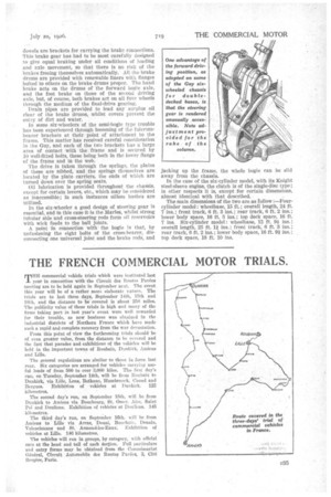
A point in connection with the bogie is that, by unfastening the eight bolts of the cross-bearer, disconnecting one universal joint and the brake rods, and jacking up the frame, the away from the chassis. whole bogie can be slid In the case of the six-cylinder model, with its Knight steel-sleeve engine, the clutch is of the single-disc type; in other respects it is, except for certain dimensions, almost identical with that described.
The main dimensions of the two are as 'follow :—Fourcylinder model: wheelbase, 15 ft.; overall length, 24 ft. 7 ins.; front track, 6 ft. 3 ins.; rear track, 6 ft. 2 ins.; lower body space, 16 ft. 5 ins.; top deck space, 16 ft. 7 ins. Six-cylinder model: wheelbase, 15 ft. 9 ins.; overall length, 25 ft. 1i ins.; front track, 6 ft. 3 ins.; rear track, 6 ft. 2 ins.; lower body space, 16 ft. 9i ins.; top deck space, 18 ft. 10 ins.