


The Parsons Light Delivery Van.
Page 8
Page 9
If you've noticed an error in this article please click here to report it so we can fix it.
Some of our readers may remember the severe strictures we passed in our early issues upon the foolishness of manufacturers attempting to delude the buying public by foisting on them antiquated pleasure chassis with attached box bodies and dubbing the productions " delivery vans."
Delivered into the hands of the Philistines certainly were the users—users is hardly correct—the unhappy sufferers who had the temerity to buy the early types of commercial motors. That time of tribulation is now quite passed, and present-day purchasers are able to buy reliable and trustworthy vehicles for loads of from TO to 20CWt. for what might be termed medium-weight carriers. But an enormous market seems to have been almost entirely neglected by the large majority of makers; we refer more particularly to the thousands of tradesmen in every part of the country who want to send out. light weights at frequent intervals and for even varying distances. What use is a thirty hundredweight capacity to the retailer who is anxious to deliver a few pounds' weight of goods at the earliest possible moment?
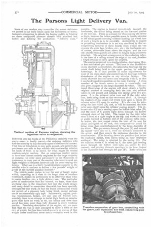
The vehicle under review is just the sort of handy motor which, appealing as it does to the large class of retailers mentioned, makes no pretensions to be otherwise than what its name implies, viz., a light delivery van. The particular point of construction that has interest, we hope, more than anything else, is the important fact that the whole design and every detail in connection therewith has been specially arranged for van work; in fact the frame construction would not permit of a pleasure body being fitted, except perhaps one of an abnormally ugly type. Framework, engine, gearing, transmission, brakes, are one and all frankly commercial; there is no attempt to lavish high finish on exterior parts that have no work to do, but labour and time thus saved has been more than fully devoted to every working portion. Premising description of the engine, etc., we mention that the van is only arranged to carry a limit of five cwt. of goods, but has been tested to carry an excess of that weight under conditions never Met ir everyday work in this country. The engine is located immediately beneath the footboards, the driver being seated on the forward portion of the van top. There is a reason for thus placing the driver so high, because the fullest possible space is thereby devoted to the actual goods carrying without making the wheel base of such a length as to be unwieldy. Accessibility to engine or propelling mechanism is in no way sacrificed by this arrangement; removal of three boards from within the van exposes the gear box, brakes, etc., etc. ; the footboards are, of course, removable from above the engine, and the two side and the front panels can either he hinged back or entirely detached. The original arrangement of the radiating tubes, in the form of a railing around the edge of the roof, provides a large amount of extra space for empties.
The engine employed is a single-cylinder, developing 7h.p. at 800 revolutions per minute. The base of the aluminium crank chamber is detachable, the adjustable bearings for the crank shaft being held to the upper portion by suitable fastenings. It is thus possible to make adjustments for wear of the main shaft and connecting-rod bearings without disturbance of the engine or any exterior fittings. The crank chamber has two arms cast integrally with it, so that it can be dropped into position on the main framing. A cross member of the frame serves to carry it rearwardly, and also gives support to the large diameter fly-wheel. The sectional illustration of the engine will show clearly a highly original method of arranging both the inlet and exhaust valves in one pocket and making one spring serve two purposes. A is the exhaust valve cam and B the inlet valve cam, both being fitted on the two-to-one .shaft. A, through the medium of the tappet rod which rests upon it, raises the exhaust valve (C) upon its seating. B is the cam for actuating the inlet valve (D), and, as will be observed, the inlet valve seats itself upon the cylinder casting proper. The exhaust valve (C) has a seating upon the hollow inlet valve (D), and the stem of C passes right down through the hollow enlarged stein of the inlet. The tappet for the inlet valve stem is bent at a right angle at the top, and works in a slot or guide formed in bottom end of the exhaust valve stem. In action, the bent tappet raises the inlet off its seat for about .one-eighth of an inch, this comparaCvely small lift being more than counterbalanced by the large diameter of the valve. The gas enters through the port (E) and around the hollow valve also to E, from the direction indicated by the arrow, and then enters the explosion chamber in the usual manner. (The drawing shows the positions just before the explosion stroke, both valves •being on their respective seating-s.) The valve is returned by the spring (G). For the exhaust stroke C is raised by A, the spent gas em ing down through the hollow inlet valve (as shown by two arrows), and passing throtwh openings in the base the .eof to the expansion box through the port (F). Both valves are
ground in when necessary in the normal way by means of a single cap at top of cylinder, which also carries a compression relief cock for easy starting. The object Mr. Parsons had in thus arranging the valves concentrically was twofold. In the first place, the exhaust valve very rarely needs grinding to its seat, because it is cooled at every cycle by the incoming charge of extremely cold gas. This is an important
consideration, but what we consider more important still is the retention of sufficient heat for the use of heavy fuel. The hot exhaust valve necessarily communicates much of its heat to the inlet valve, and, when paraffin is used, the cold paraffin spray as it enters at E at once impinges on the hot wall of the hollow portion of D, and is instantly vapourised; in fact, almost any heavier kind of fuel than petrol can be used, such as benzine, benzoline, or paraffin, etc., without carbonising the valves or leaving any deposit on the cylinder walls. It must, of course, be understood that unless a blow lamp could first be used for securing sufficient heating surface of the hollow inlet valve, petrol is essential for starting up. Upon the van we inspected last week at Southampton, two tanke are carried beneath the driver's seat, connected by a two-way cock to the fuel pipe leading to the carburetter. Over 18 months' experience with this particular method has proved the designer's theory to be perfectly correct in practice, and not a moment's trouble has occurred with this means of securing the power. We attach particular importance to this system, because paraffin is much cheaper than petrol, can be procured in every wayside village, and, by its use, fire risk is greatly reduced.
Engine cooling is attained by a simple thermo-syphon system without the use of pump or fan, and thereby another source of trouble is removed. Cold water enters around the base of the explosion chamber at H, and after reducing the heat of this, the then hot water leaves at the top of the cylinder (J). From here the water goes up by a perfectly straight and vertical pipe, which leads to the four rows of gilled radiator tubes fixed right round the two sides and rear end of the roof. After running around these, the cooled water descends by another pipe to H, and the circulation again commences. The water tank is carried on the roof to rear of the driver's seat. The usual arrangements for lubrication and ignition are fitted, the latter being of the hightension type with wipe contact, and having the induction coil adjacent to the engine, and thus saving long lengths of wiring.
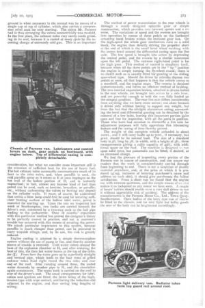
The method of power transmission to the rear wheels is through a neatly designed epicyclic gear of simple construction, which provides two forward speeds and a reverse. The variations of speed and the reverse are brought into operation by means of three pedals on the footboard actuating band brakes within the enclosed gear box. On the high-speed the whole gear mechanism runs as a solid block, the engine then directly driving the propeller shaft at the end of which is the small bevel wheel meshing with the crown bevel around the differential casing upon the live axle. The low speed is brought into action by depressing the central pedal, and the reverse by a similar movement upon the left pedal. The extreme right-hand pedal is for the high gear. This method of control is simplicity itself, because when all the three pedals are in the " up" position the engine is simply turning the fly-wheel round; there is no clutch such as is usually fitted for gearing of the sliding spur-wheel type. Should the driver by mistake depress two pedals at once, all that happens is that the vehicle conies to a standstill, and the engine stops. The reverse is obtained instantaneously, and forms an efficient method of braking. The two internal expansion brakes, attached to drums bolted to the rear wheels, are brought into action by a side lever, and are powerful enough to hold the van fully loaded on the steepest gradient. The rear live axle differs considerably from anything else we have come across; not alone because it drives only without having to support any weight, but from the fact that the oil-tight aluminium casing surrounding the bevel and differential gearing can be detached by the removal of a few bolts, leaving this important portion quite open and free for inspection, with all the parts in position. Those who have had occasion to dismantle a live axle for adjustment purposes will fully appreciate this interesting feature and the saving of time thereby gained.
The weight of the complete vehicle unloaded is about iocwt., and it will carry 'boa& up to 7cwt., if necessary, but scwt should be its normal load. The size of a standard body is sft long by 31t. in width, with a height of ft., these measurements giving a cubic capacity of 45-ft:, with additional space on the roof. The machine is designed t.) run upon solid tyres, but pneumatic can be fitted, if desired, at an increased charge.
We had the pleasure of inspecting every portion of the Parsons van in course of construction, and can assure our readers that the work in conscientiously carried through from beginning to end. There is not a suspicion of shoddy material anywhere, and, at the price at which it is produced (41[95, inclusive of lettering purchaser's name and address on each side), it should give purchasers the fullest satisfaction. From a short run we found that the engine ran with extreme quietness, and the simple means of co ,trol makes it as fool-proof as any motor we have seen. A couple of hours' tuition should enable even a very dull driver to run it without appreciable risk of accident. The address of the manufacturers is the Parsons Motor Co., Ltd., Town Quay, Southampton. Open bodies of the lorry type can of course be fitted to the chassis, and for very light but bulky goods the rear of the body can be heightened accordingly.