


Abridgments of Interesting Patent Specifications.
Page 18
If you've noticed an error in this article please click here to report it so we can fix it.
No. 20,374/ dated September arst, 1904. —H. Edmunds.—To catch dust thrown lip by the road wheels of a motor vehicle, a receptacle IA} is hung at the rear of each wheel. The side of the receptacle towards the wheel is perforated, as at 1/, and ithin the receptacle an absorbent material (di is placed. Water is fed to the receptacle from a tank (e) by a pipe (fg),
which descends nearly to the bottom of the receptacle, so that its supply is controlled on the bird fountain principle. The absorbent material becomes charged with moisture, and collects the dust thrown against it by the road wheel.
Na. 8,485, dated April aotb, 1.9o5.— Silencer.-1... W. Dantan and Anr, France. —This is so constructed that the motion of the vehicle sets up a current of air which acts inductively upon the contents of the silencer. The exhaust gases enter the compartment (1/) at a, and pass through the perforated partition Ibl) into the compartment (c); thence by the per forated partition (e), they enter the compartment (f) and escape by an outlet (k). The vehicle is travelling in the direction indicated by the arrow at (/), so that air enter ii the funnel-shaped member (h) in the direction of the arrow shown therein. The end of this funnel enters the outlet k) and and thus an inductive action is obtained.
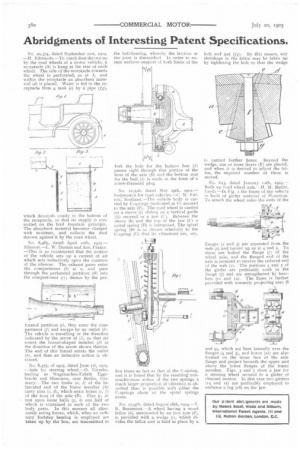
. No. 8,475, of 19o5, dated June 1st, 1904. —.Axle for steering wheel.-0. Gieseke, trading as Wagenachen-Fabrik Eggebrecht and Shumann, near Berlin, Germany.—The two limbs (a, b) of the bifurcated end of the frame member (Al carry pins (e, di, which enter boxes (e, fi of the boss of the axle ill). Pins (e, di rest upon loose balls (g, //) one half of which is contained in each of the two body parts. In this manner all alternately acting forces, which, when an ordinary footstep bearing is employed are taken up by the box, are transmitted to
the hall-bearing, whereby the friction at the joint is diminished. In order to ensure uniform support of both limbs of the
fork the hole for the bottom box (f) passes right through that portion of the boss of the axle (ft and the bottom seat for the ball (h) is made Ii the form of a screw-threaded plug.
No. 11,526, dated May 19th, 5904.— Suspension for road vehicles.—C. W. Fulton, Scotland.—The vehicle body is carried by C-springs (indicated at G) secured to the axle (FL The road wheel is carried on a sleeve (10 sliding on a vertical guide (IL) secured in a jaw (CI. Between the sleeve (b) and the lop of the jaw (Ci spiral spring (D) is interposed. The spiral spring (DI is so chosen relatively to the C-spring (C) that its vibrations are, say,
five times as fast as that of the C-spring, and it is found that by the resulting nonsynchronous action of the two springs a much larger proportion of vibration is absorbed than is possible with either the C-springs alone or the spiral springs alone.
No. 17,976, dated August 18th, a904.—T. R. Beaumont--A wheel having a .wood felloe (a), surrounded by an iron tyre (di, is provided with a wedge (c), which divides the felloe and is held in place by a bolt and nut (f g). By this means, any shrinkage in the felloe may be taken up by tightening the bolt so that the wedge i. carried further home. Beyond the wedge, one or more liners (E) are placed, and when it is desired to adjust the felloe, the required number of these is moved.
No. 623, dated January i ath, 1905.— Built up road wheel axle. —H. M. Butler, Lends —In Fig. i the frame of the vehicle is built of girder material of 1-I-section. To attach the wheel axles the ends of the flanges (a and 3) are separated from the web (t) and turned up as at 4 and 5. To these are bolted the flange (7) of the wheel axle, and the flanged end of the axle is recessed to receive the reduced end of the web (i). The portions 4 and 5 of the girder are preferably sunk in the flange (7) and are strengthened by brackets (Ii and 12). The flame is further provided with inwardly projecting ears (8
and 9), which are bent laterally over the flanges (4 and 5), and horns (to) are also formed on the inner face of the axle flange and project beneath the upper and above the lower flanges of the frame member. Figs. 3 and 5 show a jaw for a steering wheel secured to a girder of channel section. In this case two girders (14 and z5) are preferably employed to embrace a lug (t6) on the jaw.