


HOW THE ENEMY TACKLE PRODUCER-GAS PROBLEMS
Page 30
Page 31
Page 32
Page 33
If you've noticed an error in this article please click here to report it so we can fix it.
Much Experience and Resea Plant for Solid Fuels, In Illustrate Some of the Late Which British Manufactun
Been Devoted to Developing Wood. We Describe and iii German Apparatus About 6 Have Little Information IN spite of the fact that a number of elaborate systems of German producer-gas plants have been designed and tested during the past years, those for wood and diarcoal did not fulfil that which had been expected from them, namely one of the main means for rendering transport independent of imported fuel. This is exemplified by the fact that a special subsidy, in addition to a reduction in taxes, was withdrawn in March, 1938.
Producer gas seems to be the most attractive of the fuels derived from indigenous substances in respect of length of radius of operations and of mobility. Therefore, the only thing to do was to provide the country with a network of stations to supply wood and charcoal.
After initial difficulties, in particular in connection with cooling and cleaning the gases and with the adaptation of plants to the varying conditions and to give a uniform gas supply, a number of suitable plants, which give satisfactory service under normal conditions, is now on the market. Among improvements made, especially noteworthy are those which relate to enhancing the durability of the parts exposed to great heat and the action of the fire.
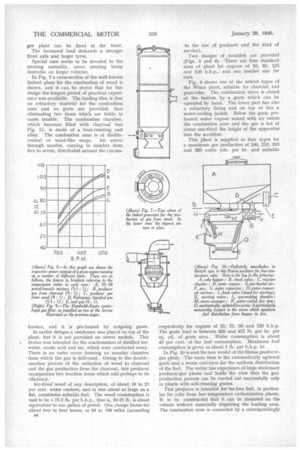
• Functioning Under Low Vacuum • Gas has to be conducted to the cylinders in a cooled and cleaned state under a relatively low vacuum, in order to give a complete cylinder filling and thereby to counter, to some extent, the unavoidable loss in engine output connected with this process (Fig. 8).
Experts are of the opinion that nearly all petrol-driven engines which fulfil the following conditions can be adapted to run on producer gas: Large-section induction pipe; sturdy transmission parts; low engine speed, and rigid engine construction, so that the compression ratio can be increased up to 8 to 1 or even 10 to 1 in extreme cases. This is necessary because producer gas shows slow burning characteristics.
Sometimes only a new set of pistons needs to be fitted to give the higher ratio, but in many cases special cylinder heads have to be used as the shape of the combus tion chamber is of considerable importance in the range of higher engine speeds.
Usually side-valve engines are not considered suitable for producer gas owing to the shape of the combustion chambers. Further, special sparking plugs have to be provided, these being adapted to the special properties of the gases. To ensure certain starting of the engine, a powerful starter and large batteries have to be used (preferably operating at 24 volts). The need for these is less, however, if arrangements permit starting on petrol.
As the gases have to be sucked by the engine, the intake resistance in the pipe lines, scrubbers and cleaners should be as small as possible. As the degree of vacuum rises, gas density falls off proportionally. Before entering the induction pipe the gas is mixed with air in a turbulent stream,usually in the ratio of 1 to 1.1 or 1.2.
• Conversion of Oil Engines • Where oil engines are adapted for producer gas—for instance in the case of a Lanova unit with a compression ratio of 12.5 to 1, the following parts have to be disconnected: injection nozzles, auxiliary air chambers, delivery piping, injection pump and fuel-filter. They are replaced by an ignition unit with drive and governor, whilst the openings of the air chambers have to be furnished with sparking plugs. It may be mentioned that the same type of engine can also be adapted for running as a petrol unit.
With regard to the question of converting liquid-fuel vehicles to run on gas, the advantage is questionable. This will be explained by an enumeration of the requirements that have to be taken into consideration. Two important factors are power loss and additional weight.
The engine has to be large enough to generate the necessary power even when the reduced output of producer gas is taken into account. (See Fig. 8.) It should have the characteristics of a high-efficiency unit. •
The vehicle must be adapted for a high front-axle load and should be of maximum width, so that the producer
gas plant can be fixed at the front. The increased load demands a stronger front axle and larger tyres.
Special care needs to be devoted to the steering assembly, servo steering being desirable on larger vehicles.
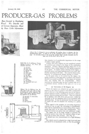
In Fig. 7 a cross-section of the well-known Imbert plant for the combustion of wood is shown, and it can be stated that for this design the longest period of practical experience was available. The leading idea is that no refractory material for the combustion zone and no grate are provided, thus eliminating two items which are liable to cause trouble. The combustion chamber, which becomes filled with charcoal (see Fig. 5), is made of a heat-resisting cast alloy. The combustion zone is of doubleconical or waist-like shape. Air enters through nozzles, varying in number from five to seven, distributed around the circum
fez ence, and it is pre-heated by outgoing gases.
In earlier designs a condenser was placed on top of the plant, but it is not provided on newer models. This device was intended for the condensation of distilled tarwater, acetic acid and tar, which were conducted away. There is an outer cover forming an annular chamber from which the gas is delivered. Owing to the double, reaction process of the reduction of wood to charcoal and the gas production from the charcoal, this producer incorporates two reaction zones which add perhaps to its efficiency.
Air-dried-wood of any description, of about 10 to 25 per cent. water content, and in size about as large as a fist, constitutes suitable fuel. The wood consumption is said to be 1.75-2 lb. per b.h.p., that is, 20-25 lb. is about equivalent to one gallon of petrol. One charge burns for about two to four hours, or 50 to 100 miles (according
136 to the size of producer and the kind of service).
Two designs of scrubber are provided (Figs. 5 and 6). There are four standard sizes of plant for engines of 50, 80, 1„20 and 150 b.h.p., and one smaller size for cars.
Fig. 4 shows one of the newest types of the Wisco plant, suitable for charcoal and peat-coke. The combustion stove is closed at the bottom by a grate which can be operated by hand. The lower part has also a refractory lining and on top of this a water-cooling jacket. Below the grate preheated water vapour mixed with air enters the combustion zone and the gas is led at about one-third the height of the apparatus into the scrubber.
This plant is supplied in four types for a maximum gas production of 180, 250, 310 and 395 cubic yds. per hr. and suitable
respectively for engines of 55; 75, 95 and 120 b.h.p. The grate load is between 326 and 355 lb. per hr. per sq. yd. of grate area. Water consumption is about 40 per cent. of the fuel consumption. Maximum fuel consumption is given as about 1 lb. per b.h.p. hr.
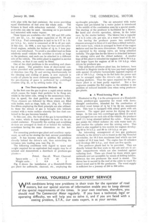
In Fig. 10 is seen the new model of the Hansa producergas plant. The•main itera is the automatically agitated grate and a worm conveyor for the uniform distribution of the fuel. The writer has experience of large stationary producer-gas plants and holds the view that the gasproduction process can be carried out successfully only in plants with self-cleaning grates.
This progucer is intended for tar-free fuel, in particular for coke from low-temperature carbonization plants. It is so constructed that it can be mounted on the vehicle without materially impairing the loading area. The combustion zone is connected by a correspondingly wide pipe with the fuel container, the worm providing equal distribution of fuel over the whole zone. The furnace is lined with refractory material. Charcoal or peat-coke can also be used. Incoming air is pre-heated and saturated with water vapour.
Three types are available—for 137, 222 and 325 cubic yds. per hr., i.e., for engine capacities of 55, 85 and 130 b.h.p. Fuel consumption is said to be 0.77 to 1 lb. per b.h.p. hr., water is consumed at 30 to 40 per cent. of this rate. In 1938, a new type for four and six-cylinclered engines, suitable for lorries of 14 to 3 tons payload, was introduced. To avoid a one-sided load on these relatively small vehicles the scrubber is nearly as large as the producer, and each can be attached to a diflerent side of the vehicle. The entire plant is supplied in service condition, so that it can easily be fitted.
One of the chief problems is the scrubbing and cleaning of gases. The primitive form of sheet-metal container provided with partitions causing abrupt changes of direction (see Fig. 5) and serving simultaneously for the cleaning and cooling of gases, is now replaced in nearly all plants by more elaborate apparatus. Usually the pre-cleaning of gases is performed by centrifugal cleaners (Fig. 9), or by settling tanks (Fig. 6).
• Two Dust-separation Methods •
In the first case the gas is given a rapid rotary motion which causes the larger dust particles to be flung out, whilst in the latter case, owing to the momentary reduction in speed, the dust particles are caused to fall. These cleaners are followed by filters which are filled with bodies, such as rings, balls, etc. (Fig. (3). Further fine-filters employing the fluid principle are also utilized. In these the stream of gas is brought into intimate contact with a water surface whereby the fine dust contained in the gas becomes bonded.
In this case, also, the heat of the gas is transmitted to the water, which in turn dissipates its heat via its aircooled container. Frequently the cooling and scrubbing devices are arranged in front of or behind the radiator, sometimes having the same dimensions as the lastnamed.
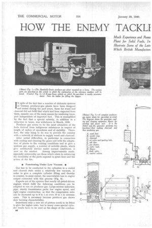
For mounting producer-gas plant and auxiliary equipment, as well as for storing the fuel, several possibilities exist. It has become usual to position the producer directly behind the driver's cab, thus minimizing the intrusion into loading area (see Fig. 2).
The following conditions with regard to space and weight required for an equivalent fueI supply may be of interest and demonstrate a drawback of producer-gas plants:— Fig. 3 shows the installation of a Humboldt-Deutz gas plant for anthracite, charcoal, etc., employing the up-draught principle. The air saturated with water
vapour and pre-heated by a water jacket is introduced in the middle of the combustion zone by a special nozzle. The starting of the producer is facilitated by a blower, for hand and electric operation, driven, in the latter case, by the starter battery. The blower has a capacity of 4 to 5 cubic yds. per rain. at a water head of 3i ins.
Gas leaving the producer passes two centrifugal cleaners arranged in front of it and then a ribbed radiator, with water tank, which is arranged in front of the engine radiator and has the same dimensions. From this the gas is conveyed to the mixing valve, air being admitted radially. The pipe line for the blower is detached between the mixing valve and the ribbed radiator. A smaller type of this plant is intended for engines of SO to 70 b.h.p. and larger types for engines of 80 to 110 b.h.p. when driven by producer gas.
This anthracite producer plant has, for instance, been installed in Magirus trucks of 64 tons pay-load equipped with special 12-cylinder horizontally opposed engines of 110 or 150 b.h.p. Owing to its flat form the power unit can be arranged under the driver's cab, or under the loading platform. Thus the space required for the pro ducer plant is at least partly regained. Not a few engineers consider the flat engine as the solution to the problem of reduced loadable area when using producergas plants.
• A Wood-burning Plant •
Illustrated in Fig. 1 is the arrangement of a HumboldtDeutz producer-gas apparatus for wood with down: draught combustion, intended for the combustion of air-dried wood lumps of l by 2 by 21 ins. maximum size. This type is equipped with rotary grate with ash remover. The upper part serves for drying the wood limps. In this case two centrifugal gas filters (2 and 3) are arranged one on each side of the vehicle, the producer itself (1) being situated behind the cabin. From there gas passes the ribbed radiator (4) with water tank (5) and reaches the cylinder over the mixing valve. This plant is also supplied in two models for engines developing 50 to 70 b.h.p. and 80 to 110 b.h.p. on gas.
An interesting arrangement of two gas producers virtually in the driver's cab is found in the big lienschel six-wheeler, for 18.2 tons maximum load which can tow a trailer of 16.2 tons load. The engine has 12 cylinders and develops 250 b.h.p,, and there are five speeds_ Two producer plants had to be provided. They are directly behind the four seats in the cab and are in airtight compartments which are also insulated against radiating heat. These are closed by doors which open outwards and are accessible by means of folding ladders. Between the two producers the wood is stored. The driver has to ascend to the roof of the cabin to reach the stored wood and to fill the producers. The wood supply is sufficient for a journey of 250 to 300 miles.