


A New Infinitely Variable Gear
Page 52
If you've noticed an error in this article please click here to report it so we can fix it.
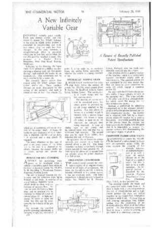
INFINITELY variable gears usually 1 fall into distinct classes, and one shown in patent No. 592,661 belongs to the 'class in which rotary motion is converted to reciprocating and back into rotary after the ratio has been changed. In this case, however, a straight-through drive is provided, which can be put into action when the variable gear has reached its peak. The patentee is J. Wooler, Willow Bungalow, West End Road, Ruislip, Middlesex.
Referring• to the drawing, the input shaft (1) is splined to a sliding member carrying a sloping shaft (2); this passes through, and controls the stroke of, an eccentric (3). This adjustment can be made externally by a screw (4).
The, eccentric sheave carries four spaced arms (5) which actuate four rocker shafts (6). These oscillate through an angle determined by the setting of the eccentric, and each is linked to one of four free wheels (7), which act in succession and cause rotation of the output shaft. A brake (8) holds the gear stationary when a reduction is required, but for a direct drive it is released and a dog clutch (9) engaged. • The usual objection to this type of gear is the jerky nature of the drive, but in this case it is claimed to be absent, because the rocker shafts act as torsion springs and absorb the shocks.
POWER FOR HILL-CLIMBING
ADEVICE for permitting more power to be developed when a vehicle is travelling uphill than when on the lever is shown in.patent No. 593,875, by H. Houlding, 5, Woodlands Terrace,
Fulwood, Preston, Lancs. •• The unit is located between the carburetter and the induction pipe, being flanged to suit both. It consists of an out-of-balance butterfly valve which' tends to close with an increase of mixture flow. An external arm (1) forms a limit stop, and its position can be adjustea by means of a pair of con.eal plugs (2). A light coil spring (3)' tends to open the valve, but this can be overcome by the velocity of the gas floW.'
-To' provide the required gravity-operated adjustment, a swinging weight (4), pivoted at A34
point 5, either adds to, or subtracts from, the spring force, according to whether the vehicle is sloping downhill Or up.
HYDRAULIC TIPPING GEAR
A HYDRAULIC mechanism for a tipI ping body forms the subject of patent No. 593,704, which comes from R. Carley, 38, Bradford Avenue, Great Lever, Bolton, Lancs. The mechanism is of simple design and has few movingparts.
The drawing shows the ram and its associated parts, for which power is provided by an oil pump attached to the gearbox. The ram piston (I) moves in a cylinder which is integral with a second larger cylinder; this leaves a space (2) which is used as an oil reservoir, no external tank being required. A loop of piping runs to the pump and the control valve. only one pipe has to withstand high pressure. The second pipe can be made from rubber, thus reducing the risk of fracture.
In operation, the oil forces the piston upwards, and presses on a beam (3) pivoted about a pin (4). The beam transmits the force to'the body through rollers running in track grooves (5). A limit valve (6) allows Oil to escape from the cylinder when the piston uncovers it at full stroke.
FREE-PISTON COMPRESSOR
THE modern trend towards the pressure charging of oil engines creates interest in all types of compressor. Of these, the free-piston pattern is unique, because, although it is a prime mover, it has no revolving parts. The latest suggestions in design are put forward in patent No. 594,013 by R. Pescara,
Lisbon, Portugal, who has made considerable research into the subject.
The drawing shows a general outline of the machine, which is a horizontally opposed two-stroke engine with no rotating parfs. The opposed pistons are not restrained in any way, except that they are timed to exact opposition' by racks (1) which engage a common pinion (2).
An inner cylinder (3) forms the power unit, whilst a large cylinder (4) acts as the pumping unit. The large cylinder at the other end (5) is a rebound chamber which stores the energy' for the next compression stroke.
Starting is performed by admitting compressed air to the rebound cylinder se as to drive the pistons -inwards on the first compression stroke: An injector (6)2 is supplied with fuel by a single' stroke pump (7) worked by a rocking bell-crank. To prevent possible damage to the pistons when the injector has been removed, the engine is so designed that it is 'impossible to remove the injector without first disconnecting the starting-air supplS, at point 8.
COMPOSITE FABRICATED VALVE CCORDINGto patent No. 593,709.
the head of a valve should be faced with anti-corrosive metal, whilst the stem requires. the property of hot strength. A known manufacturing process is to weld a layer of nickelchrome on to the head of a standard valve, but • this is said to be a costly operation. An improved method is described by the patentee, Eaton Manufacturing Co., Cleveland. Ohio, U.S.A., in this specification.
The drawing depicts the blank and the completed valve made from it. A start is made with a corrosion-resistant disc (I) of nickel-chrome and a hightensile portion (2); these are Melted together in an oxygen-free atmoiphere to form a solid blank. Various forging and piercing operations then follow. ending with the production of the finished valve (3), which is of the hollow pattern. the disc effectively covers 'the head to form a protective coating, yet the valve is a one-piece structure.