


A NEW SYSTEM OF LUBRICATION.
Page 32
If you've noticed an error in this article please click here to report it so we can fix it.
A Résumé of Recently Published Patents.
Ninety per cent. of the troubles which arise in connection with the use of machinery, occur as the result of inefficient lubrication, and this remark applies particularly in connection with motor veinclot of all kinds and types. It will be granted, therefore, that anything that is designed to increase the facilities for adequate lubrication, whilst, at the same time, lessening the demand foe. Wefttion to that operation on the part of the user of the machine, is likely to he of particular interest to our readers.
Such a device is that which is patented by H. Garner and others, and which is described in specification No. 170,639. This invention deals with a particular phase of the subject.. The device which is described. is, sae a matter of fact, more particularly applicable to slow-moving wheels or bearings in whichrotation actually takes place round a fixed shaft, the circumstances of use being such that the speed of rotation is not sufficient to ena.hle the rotating part to carry with it the requisite amount of lubrication., without sonic special provision being made to assist that function.
It is with the provision of special means of carrying lubricant that this particular patentsis.concerned, more particulaidy with reference to that kind of lubricating apparatus wherein what may be called a closed circulation of the lubricant is obtained. A reservoir for the oil is provided, and in addition.there is a vane or eleNator which rotates in the. reservoir and elevates a small quantity of the oil at each revolutions depositing it within a suitable receptacle from which passages are arranged for conveying the lubricant to the shaft or bearing which is required to be lubricated. In addition, special means are provided at the ends of the hearing to prevent .escape rd the lubricant and passages are also provided to allow the lubricant to leave tho bearing and return to the reservoir, these passages being so arranged as to increase the probability that the lubricant will traverse the whole of the bearing which requires to be lubricated before leaving it.
The inventors point outthat it is well known that in practically all cases the load is generally borne upon about half of the circumference of the bearing, the fit of the surfaces of the hearings on the other half being comparatively. slack, and it is at the slack side of the bearing, where there is no load, that the lubricant is more easily able to enter the hearings; consequently one of the features of t.he invention is that the lubricant is led to this part of the bearing. In some cases, as, for example, the hub of the front wheel of a tractor, upon which the axle rests, the slack part of the bearing Will be on top. In other cases, as, for example, the pulley front which the belt is suspended and the pull taken in a downward direction, the slack part will he underneath. In other cases it may be at, the side.
There are 16 illustrations published in connecton with this specification; they show various applications of the principle to bearings of different, kinds, and for different purposes, such as bearings for the disc coulter of a plough, bearings for the wheels of a tractor, and for belt pulleys. The illustrations and examples -534 are selected to show how, in some cases, the lubricant is led in at the tiap and distributes itself over the shaft. In another case the lubricant is introduced at the side, and in another underneath.
Some of the illustrations show the oil being filtered as it returns to the reservoir, in others the filter is disposed above the receptacle from which the oil
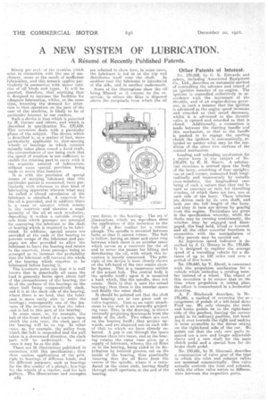
runs direct to the bearings. The set of illustrations whirls we reproduce show the application of this invention to the hub of a disc coulter for a, tractor plough. The spindle is 'mountedbetween forks so that it cannot rotate. The hub is hollow, having an inner and outer ring between which there is an annular space which servos as a reservoir for the ml and to cover the means for lifting and distributing the oil, with which this invention is mainly concerned. The principle of the device is most clearly shown on the left-hand of the twe centre circular figures. This is a transverse section of the actual hub. The central body is the spindle itself ; upon it is mounted a bush which, like the spindle, does not, rotate.' Next to that is seen the actual bearing ; then there is the annular space and finally the outer shell.
It should be pointed out that the shell and bearing. are hr one piece and revolve together. Cast as an outer attachment to the shell is an inwardly projecting vane. This, in the drawing; is shown vertically projecting downwards from the inside of the shell. Two others are cast on the bearing itself ; they project upwards, and' are disposed one on each side of that to which we have already referred. A gap is cut through the space between these two vanes, and as the bearing rotates the outer vane gives up a supply of lubricant, whence the oil flows on to the bearings being aided in its distribution by helieoid grooves cut on the inside of the bearing, thus practically insuring that the oil flows from the centre of the spindle, where it is introduced to the outer ends, leaving finally through small apertures at the end of the. bearing.
Other Patents of Interest.
No. 170,658, by C. K. Edwards and others, including Associated Equipment. Co., Ltd., describes an automatic method of controlling the advance and retard of an ignition member of an engine. The ignition is controlled ;collectively in accordance with the mevement, of the throttle, and of an engine-driven governor, in such a manner that the ignition is advanced as the engine speed increases and retarded as that speed decreases, whilst it is advanced as the. throttle valve is opened and retarded as that is
closed. Additionally, a connection is made between the starting handle and this mechanism, so that. as the handle • is pushed in to engage the starting clutch the ignition is automatically, retarded no matter whatmay be the condition of the other two sections of the control mechanism.
Loading and unloading mechanism for is motor lorry is the subject of No. 170,674, by E. M. islunres A substantial structure is erected upon the body of the lorry, consisting of four uprights, one at each corner, connected both longitudinally and transversely by suitable cross-members, the longitudinal ones being of such a nature that, they can be need as runways or rails for travelling winches, of which there are. two, one at each side of the lorry. These *inches are driven each by its own shaft, and both run the full length' of the lorry, and they in turn are drivenby gearing froth the. engine. Particulars are given in the specification whereby, while the shafts may be running continuously, the winches may be eneaged.•-and `disengaged, the loth held, lifted or lowered. and all the other essential functions in connection with the manipulation of bulky. parcels may be carried. out. An ingenious speed indicator is described by J. G.. Rinney inNo. 170,636. It is designed to register the . average speed of a travelling vehicle for a distance of up to 150 miles and over a period of five hours.
No. 170,640, -by V. Zbrail, is concerned with the propulsion mechanism for a vehicle which embodies a striding member instead of a wheel. The object of this invention is to' ensure that at the time when propulsion is taking place the effort is concentrated in a horizontal direction. .
A. F. Hitchcock describes, in Nes 170,660, a method of reversing the arrangement of pedals of a left-hand drive Ford ear. Ho only changes the main and brake pedals on to the right-hand eide of the gearbox, leaving the reverse pedal in its ordinary position, but bending it over towards the right and making it more accessible to. the driver sitting on the right-hand side of the car. Ho, points out that the only new parts required are a new and longer adjustable sleeve and a new shaft for the main clutch pedal and a Special boss for the brake shaft pedal.
No. 170,681, by M. Giannati, describes a construction of valve gear of the type in which the inlet and exhaust valves are mounted concentrically. One valve actually controls the inlet and exhaust, . while the other valve serves to differentiate between the respective ports.