


ROADSIDE AND GARAGE.
Page 31
If you've noticed an error in this article please click here to report it so we can fix it.
A Page for Drivers, Mechanics and Foremen.
Two Useful Garage Accessories.
The sender of the following comingaticationhas been awarded the extra. payment of 5s. this we e
(2332) " Hannibal " (Guist) writes
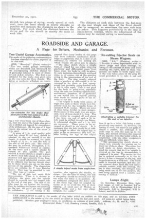
The two useful garage' accessories., which are described and illustrated..bv: the accompanying sketches should be of particular interest to users of Dahl:1.e le,r and A.E.E. vehicles. The first is an extractor for the. bike shoe pivot Pins en the rear axles for these chassis: The driver or mechanic willefued, on reinov ing a rear wheel from one of these chassis, that the end of the brake shoe pivot. pin is drilled and tapped for convenience of its withdrawal. (In the case of Y type chassis the actual size of the screw is -3 in. gas.) " A piece of a in. good quality mild steel bar, about 12 ins. long, Should be selected. At the end marked B on the sketch, it should be screwed, for about a length of 11 in., to suit the bolo in the end of the pivot pin.The remainder may be screwed, throughout, in. standard Whitworth thread or :similar. At the outer end a square should be formed on this spindle_ The part marked A on the sketch is simply a piece of drawn steel tulle about 1.1 in. interior diameter and approximately 9 ins. long. Part. C is a good substantial washer, and D an ordinary nut having threads similar to those which are cut. on the mein portion of the spindle. The dimensions given are suitable for Y type Daimler chassis. They may be amended to suit any other type of vehicle.
"The use of 'this tool needs little demonstration. When it is desired to withdraw the pivot pin, the .spindle should be screwed into the tapped hole at the end of that pin. The end of the tube .rauet be set against the housing, then, by holding the square and screwing up the nut, the pivot pin may readily be withdrawn. (I am taking it for
granted that, -every reader, of this page. will haves sufficient mechanical knowle)ige .to._appreciate that it. is-first of .all necessarylto remove the locking pin which retains the pivot pin in place). 1" The other sketch shows a .simple form of triphd for use when removing .gitargoxes. and differential cases." from buses when the ' bedyeis . still in.Adace. IA such instances-thetordinary overhead crane is, of course, out of the, question owing to the intervention of the roof of the body. The plan usually adopted when a gearbox or differential is to be removed -is for three or four strongarmed but probably grimy-handed men to lift it with ropes. This is not good for the body or paint-work, especially when the men are working against/time, and ceantiot, therefore, be so particular as one would like as regards placing their hands on various parts of the interior of the bus.
tripod' is made from pieces of angle Mon such as those which were frequently used for the tarpaulin hoops of standard W.D. lorries. There are some of these lying derelict in most garages. Three pieces of this angle iron are necessary, each of them about 5 ft. long. The ends should be rounded off and about 2 ins, from one end of each a 1.1 in. hole truist be drilled through 'one flange. A substantial shackle and a 1 in. bolt are necessary. e These parts to lee arranged as_ shown in the sketch. It is necessary that the bolt should be of sufficient length to allow the tripod legs to splay as far as necessary ; this bolt, be. ;sides holding the legs of the tripod together, also supports the shackle, as shown. For the sake of safety, the end of the pulley should be riveted over the nut when the latter is in position. As an. additional safeguard the lower ends of -the .three legs mey be. coupled by chains so as to avoid the risk of their slipping. A small pair of Wee-ton or similar blocks and a few rope slings complete the outfit." -Re-cutting Injector Seats on
Steam Wagons.
f2333) " ILL." (Plaistow) writes Trouble is .often experienced -with injector plugs and their seatings, as, owing to the amount/of force used when shutting the valve, bah of these components are liable to fairly rapid wear. If the wear takes place an the plug the usual procedure is to -take it out and true it up in a lathe, this-being a .cornparatively easy -patter. If, however, the seating is worn, the repair isnot quite. so simplea matter, for, although •t is quite easy to true the seat. up in the lathe, this method involves the removal of the injectoi from the 'boiler which, in
conjunct-sec, the Gates components that.are affcted, takes time
" The accompanying sketch shows a simple tool, whereby the 'seating can be trued up while,in place 'Thecotter bar itself needs no detai: description, beyond the r.emerit that. its in. spindle is screwed at the top, to .accommodate eimpleeof 3 in mites. The carrier for the bar is screwed externally to fit. the injector; it,has a hexagon at.the,top, and in .use it serves as a feed tool.. The whole outfit is inserted together, and the carrier -screwed down ;until the tool makes suitable contact with the seating, the bar is then revolved, the hexagon nuts being made use of for this purpose, the feed being applied until a suitable new seating is formed."
Lamps Alight.
On Saturday, December 241h, light your lamps at 4.22 in London, 4.8 in Newcastle, 4.25 in Birmingham, 4.8 in Edinburgh, 4.25 in Liverpool, 4.32 in Bristol, and 5.6 in Dublin.