


Damped Suspension Unit for Heavy Loads
Page 36
If you've noticed an error in this article please click here to report it so we can fix it.
,PATENT No. 554,386, from Automo• tive Products Co., Ltd., the Ribbesford Co., Ltd., and others, all of Tackbrook Road, Leamington Spa, concerns a suspension and shock-damping unit. Intended for heavy loads', the device is shown as applied to the track Support rollers of a crawler-type vehicle.
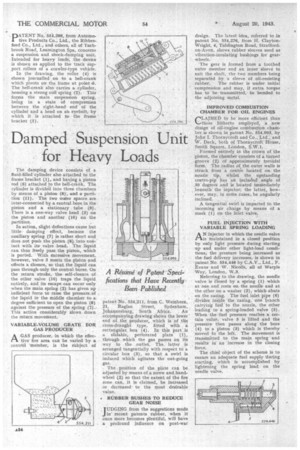
In the drawing, the roller (4) is shown journalled on to a bell-crank which pivots on the frame at point The bell-crank also carries a cylinder, housing a strong coil spring . (2). This forms the main suspension spring, being in a state of compression • between the right-hand end of the cylinder and a head on an eyebolt, by which it is attached to the frame • bracket (I).
The damping device consists of a fluid-filled-cylinder also attached to the frame bracket (I), and haying a piston rod (6) attached to the bell-crank. The . cylinder is divided into three chambers by means of a piston (8), and a partition (11). The two outer spaces are inter-connected by a central bore in the. piston and a stationary, tube (9). There is a one-way valve head (3) on the piston and another (10) on the partition.
In action, slight deflections cause but little, damping effect, because the auxiliary spring (7) is rather short and does not push the piston (8) into contact with it valve head. The liquid can thus freely, pass the piston, which is ported. • With Excessive movement, however, valve 3 meets the piston and effects a closure, se that the liquid can pass through. only the central bores. On the returnstroke, the self-closure of the other valve (10) traps the liquid entirely, and its escape cap occur only when the main spring (2) has ,given up 'sufficient force to raise the pressure,of tU liquid in the middle chamber to:a degree sufficient to open the piston -(8) against the pressure of the spring (2).This action considerably slows down
the return movement. • VARIABLE-VOLUME GRATE BOR GAS PRODUCER
AA GAS producer, in which the effective fire area can be varied by a control "member, is the subject of
patent No. 554,211, from C. Weinbren, 21, Raglan Street, Sydenham, Johannesburg, South Africa. An accompanying drawing shows the lower end' of the producer, which is of the cross-draught type, fitted with. a rectangular box (4). In this part is
• a slidable, perforated plate (1), through which the gas passes an its way to the _outlet. The latter iS arranged tangentially with respect to a circular box (3), so that a swirl is induced which agitates the out-going gas.
The position of the plate can be adjusted by means of a screw and handwheel (2) so that the extent of the fire zone can, it is claimed, be increased or decreasedto the most desirable value.
• ROBBER BUSHES TO REDUCE GEAR NOISE TUDGING from the suggestions made J in" recent patents rubber, when it once more becomes plentiful, will have a profound influence on post-war design. The latest idea, referred to in patent No. 554,276, from H. ClaytonWright, 4, Tiddington Road, Stratfordon-Avon, shows rubber sleeves used as vibration-insulating bushings for gear• wheels.
The •gear is formed from a toothed outer member and an inner sleeve to suit the shaft, the two members being separated by a sleeve of oil-resisting rubber. The rubber is under initial compression and may, if extra torque has to be transmitted, be bonded to the adjoining metal.
IMPROVED COMBUSTION CHAMBER FOR OIL ENGINES CLAIMED to be more efficient than those hitherto empIeyed, a new design of oil-engine combustion chainberis shown in patent No. 554,093, by John I, Thornycroft and _CO., Ltd., and W. Dack; both pf Thornycroft: House, Smith Square, London, S.W.1.
Formed entirely in the crown of the piston, the 'chamber consists of a turned groove (2) of -approximately toroidal form. The radius Of the outer walls is struck from 'a centre located on the nozzle tip. whilst the upstanding centre-pip has all included • angle of .30degree's and is loCated. iminediately beneath the injector; the latter, however, may, in some -cases,. be angularly inclined.., A tangential swirl is imparted to the incoming air charge by means of a mask (I) on the inlet valve . FUEL INJECTION WITH VARIABLE SPRING LOADING injector in which the needle valve is Maintained in a closed 'position by only light pressure -during starting -up and under other light-load conditions, the ,pressure being increased as the fuel delivery increases, is shown in --patent No. 554,446 by C.A.V., Ltd., F. Evans and W. NicelIs, all of Warple Way, London, W,3.
Referring to the drawing, the needle valve is 'dosed by a spring (1) which at one. end rests on the needle and at the other on a washer (2), which abuts on the casing. The fuel inlet pipe (6) divides inside the casing, one branch carrying' fuel to the nozzle, the ether leading to a spring-leaded valve (5). When the ,fuel pressure reaches a certain ,value, valve 5 is lifted and the pressure then passes along the bore (4) to a piston (3) which is thereby moved to, the left. The movement is transmitted to the main spring and results' in an increase in the closing force.
The chief object of the scheme is to ensure an adequate fuel supply 'during starting, which ' is accomplished by lightening the spring load on the needle valve.