


An Opposed-piston Two-stroke Oil Engine
Page 78
If you've noticed an error in this article please click here to report it so we can fix it.
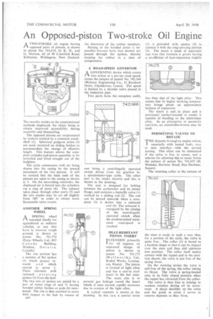
A TWO-STROKE oil engine having 1-1 opposed pairs of pistons, is shown in patent No. 741,619, by B., D., and G. Morton, all of40 Crawford Road, Kilburnie, Wellington, New Zealand.
The novelty resides in the constructional methods employed, the object being to obtain improved accessibility during assembly and dismantling.
The opposed pistons arc reciprocated by rockers worked by a common crankshaft (1). Spherical gudgeon joints (2) are used, mounted on sliding bushes to accommodate the change of effective length. This feature allows the complete cylinder-and-piston assembly to be unbolted and lifted straight out of the bedplate.
The cycle commences with air being drawn into the casing by the inward movement of the two pistons. It will be noticed that the back ends of the pistons are open to the casing as shown at 3. On the succeeding outstroke, the displaced air is forced into the cylinders via a ring of ports (4). The exhaust takes place through other ports (5) and the two cranks may be set off slightly from 180' in order to obtain more favourable valve events.
ANOTHER SPRING WHEEL
ASPRING wheel intended chiefly for agricultural or military vehicles, or any that have to traverse rough ground, is shown in patent No. 741,752 (Enjar Wheels, Ltd., 802 Canada Building, Windsor, Ontario, Canada).
The rim portion has a number of flat spokes (1) which project inwards and which extend to point 2. These alternate with outward pointing spokes (3) from the hub. The two sets of spokes are wilted by a pair of metal rings (4 and 5) having bonded rubber bushes or pads (6) interposed. The rim is thus enabled to move with respect to the hub by reason of a44 the distortion of the rubber members.
Parting of the bonded joints is impossible because bolts (not shown) are passed through the spokes, thereby keeping the rubber in a state of compression.
A ROAD-SPEED GOVERNOR A GOVERNING device which comes /-1 into action at a pre-set road speed, forms the subject of patent No. 742,166 (Walmor Engineering Co., 13 Kershaw Drive, Chadderton, Lancs). The speed is limited by a throttle valve placed in the induction pipe.
Two parts form the complete outfit, one being a centrifugally operated switch driven from the gearbox by a speedometer-type cable. The other part is the intake throttle and this is shown in the drawing.
The unit is designed for bolting between the carburetter and its intake flange, and contains a butterfly valve (1) worked by a sliding rod (2). The rod can be moved upwards when a corepiece (3) is drawn into a solenoid coil (4). The solenoid is energized by the closing of the centrifugally operated switch when the predetermined maximum road-speed is reached.
HEAT-RESISTANT PISTON INSERT INTENDED primarily for oil engines, an improved 'design of piston is shown in patent No. 741,173 (Wellworthy, Ltd., Radial Works, Lymington, Hants). The piston is formed of light alloy and has a cast-in steel insert in the hot zone. The main aim is to prevent gas leakage round the insert which, if once started, rapidly increases due to erosion of the light alloy.
A typical example is shown in the drawing. In this case a central torus (1) is provided with spokes (2) to connect it with the ring-carrying portion (3). The insert is made of austenitic cast iron (the formula is given) having a co-efficient of heat-expansion slightly less than that of' the light alloy. This means that its higher working temperature brings ,about an approximate balance of expansion.
The insert is cast in place and is previously surface-treated to render it capable of bonding to the aluminium alloy. As an alternative to austenitic cast-iron, an aluminitim-bronze may be used.
PERMITTING VALVES TO ROTATE
THE deposits formej on engine valves, especially with leaded fuels, may in time interfere • with the correct seating. This effect can be minimized if the valve is free to rotate, and a scheme for allowing this to occur forms the subject of patent No. 741,437 (H. Weslake, Harbour Road, Rye Harbour, Sussex).
The retaining collar at the bottom of the stem is made in such a way tha , for a portion of the cycle, the valve is quite free. • The collar (1) is bored to a keyhole shape so that it can he slipped over the stem and then slid sideways into position. The collar itself makes contact with the tappet and in the position shown, the valve is just free of the spring force.
On the working stroke the valve is still free of the spring, the collar taking its thrust. The valve is spring-loaded only in its fully closed position when the tappet has retracted from the collar.
The valve is thus free to indulge in random rotation during all its movement. A sharp shoulder on the valve and the guide at point .2 serves to remove deposits as they form.