 1
1 2
2 3
3 4
4 5
5 6
6 7
7 8
8 9
9 10
10 11
11 12
12 13
13 14
14 15
15 16
16 17
17 18
18 19
19 20
20 21
21 22
22 23
23 24
24 25
25 26
26 27
27 28
28 29
29 30
30 31
31 32
32 33
33 34
34 35
35 36
36 37
37 38
38 39
39 40
40 41
41 42
42 43
43 44
44 45
45 46
46 47
47 48
48 49
49 50
50 51
51 52
52 53
53 54
54 55
55 56
56 57
57 58
58 59
59 60
60 61
61 62
62 63
63 64
64 65
65 66
66 67
67 68
68 69
69 70
70 71
71 72
72 73
73 74
74 75
75 76
76 77
77 78
78 79
79 80
80 81
81 82
82 83
83 84
84 85
85 86
86 87
87 88
88 89
89 90
90 91
91 92
92 93
93 94
94 95
95 96
96 97
97 98
98 99
99 100
100 101
101 102
102 103
103 104
104 105
105 106
106 107
107 108
108 109
109 110
110 111
111 112
112 113
113 114
114 115
115 116
116 117
117 118
118 119
119 120
120 121
121 122
122 123
123 124
124 125
125 126
126 127
127 128
128 129
129 130
130 131
131 132
132 133
133 134
134 135
135 136
136 137
137 138
138 139
139 140
140 141
141 142
142 143
143 144
144 145
145 146
146 147
147 148
148 149
149 150
150 151
151 152
152 153
153 154
154 155
155 156
156 157
157 158
158 159
159 160
160 161
161 162
162 163
163 164
164 165
165 166
166 167
167 168
168 169
169 170
170 171
171 172
172 173
173 174
174 175
175 176
176 177
177 178
178 179
179 180
180 181
181 182
182 183
183 184
184 185
185 186
186 187
187 188
188 189
189 190
190 191
191 192
192 193
193 194
194 195
195 196
196 197
197 198
198 199
199 200
200 THE SEARCH FOR PERFECTION
Page 103
Page 104
Page 105
If you've noticed an error in this article please click here to report it so we can fix it.
HOW long does it require to produce a new design of chassis, what steps are taken to safeguard the buyer against faulty construction, and why cannot prices be reduced by modern methods of production? These and other such questions are raised at meetings of road transport engineers in all parts of the world. There is no set solution of these problems, because of the variations in manufacturers' policies, in the amount of income that is to be ploughed back in experimental and development research, and the methods of production employed.
Some makers prefer to assemble their vehicles with proprietary ready-made engines, gearboxes and other components, and, employing these units, a research or development department would be an unnecessary expense, because all such work would be carried out by the suppliers. The introduction of a new or modified range of models in this case would take a relatively short time, depending on the availability of the proprietary units.
The larger concerns, as a rule, design and build prototypes and subject them to stringent trials before commencing production of a new vehicle. After the high expense involved in designing and producing prototypes and a range of production models, the makers might be excused if they cut their unproductive labour costs and continued to build the same type for several years before contemplating any radical change.
This, however, is not British policy. The prototype stage is followed by development work to improve the model wherever possible, and to incorporate the latest ideas, thus giving the customer the greatest value for money and increasing the life and efficiency of his fleet.
The larger manufacturer cannot afford to be without a development department, because if any unit be not fully proved, even after the slightest modification, a large number of vehicles may be delivered before any weakness becomes apparent. Again, any manufacturer who is to take responsibility for his products can do so only if he has previously satisfied himself by testing the reliability of each unit. Unlike British justice, which assumes that a prisoner is innocent until he is proved guilty, the development engineer invariably regards any alteration with suspicion until it is proved beyond doubt.
Such is the practice of Leyland Motors, Ltd., Leyland. Lanes, which designs and produces a range of goods and passenger models from the Comet medium-capacity four-wheeler to the Octopus maximum-load eightwheeler, models which are renowned throughout the world for typically British thoroughness in design.
At Leyland, vehicles are made to customers' requirements. This policy is reflected in a range incorporating 70 goods and passenger models of varying size, capacity and wheelbase dimensions. Suggestions for a new model are first made by the sales organization, usually after a survey of the markets, at a meeting with the Leyland design committee. Permanent members of this board are Mr. H. Spurrier, managing director and chairman of the committee, Mr. W. West and Mr. S. Markland, joint general managers. The chief engineer, sales manager and works manager are co-opted to broaden as much as possible policy on new designs and development.
Planning Prototypes If the suggestion for a new model appears sound, the design committee draws up a provisional specification, which is passed to the chief designer for drawings to be made. The engineering and designs divisions are under the control of Mr. N. Tattersall, who is acting chief engineer. The drawings are submitted to the board for discussion and approval, and when they are finally sanctioned the research department prepares to build components for several prototypes. Each step of development in the research department is made in conjunction with the drawing office and modifications are made to the original drawings as required.
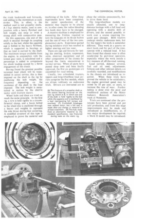
Engine capacity is predetermined by its required output, given the gross weight and transmission ratios. The power output per litre or cubic inch is known from the current design. Often the power unit can be a scaled version of an existing engine, and after the assembly is complete can be proved on the test bed, provided that no radical change has been made in the design. This test-bench work is not accepted as being a complete guarantee of efficient running, and is combined with a long period of work on the chassis under various conditions of operation.
As an example of experimental engine test procedure at Leyland, the most recently developed unit had 200 hours' running at the normal rate, after which it was speeded up to the sixth harmonic, 2,350 r.p.m. At this point, every part tends to vibrate and because no defect was found during 200 hours' of this treatment, it was cycled at one-hour intervals for a further 200 hours at speeds of 1,500 r.p.m. and 2,500 r.p.m. As a final, but fruitless, attempt to explode the engine, the cycling speed was raised to 1,700 r.p.m. and 2,700 r.p.m. for 220 hours. This power unit is normally governed to 2,200 r.p.m. for normal road operations.
Any weakness in the basic construction would be exposed during these trials, but failures, which may be attributed to continuous cold starting, can best be found in operation. Therefore, these trials are not considered complete when the first unit leaves the test bed.
While the engine is being tested, the assembly of prototypes is proceeding, and as they become available, their component parts are each in turn subjected to severe tests on home-made rigs.
At Leyland the designers consider that a goods model should have a
resilient frame, whereas the passenger chassis has to be a rigid structure, having relatively little twist which might add to the wear and
tear of an expensive body. Bars through the front and rear spring eyes of the Comet goods frame can be twisted independently through an angle of 25 degrees without causing harm to the structure.
In developing this chassis frame, the cross-members are formed from steel pressings, which are attached to the side rails by cold-squeeze riveting, whereas the more rigid passenger version is braced by a larger number of tubular and pressed-steel members New and current-design transmission units are subjected to severe trials in the prototype research, and tests are continued in production development stages. Proof of the reliability of these components is found in the infrequent need for clutch adjustments or the replacement of worn or broken parts in Leyland models. Prototype clutch assemblies are bench tested in the experimental department, the acceptance standard being 500,000 fierce engagements, during which the internal temperature may rise up to 400 degrees C. without need for major attention.
Transmission Test Rigs Gearboxes are proved in pairs on a rig, in which two boxes are connected back to back, one being driven by a motor, and the torque through the second being absorbed by a motor generator. The speed and load of the motors can be controlled, and torque far in excess of the standard engine output can be passed through the gearboxes to accelerate the effects on the road in a comparatively short period.
Another rig used for testing the synchronizing gear of the Leyland passenger-chassis gearbox has a robot action which operates the clutch and moves the lever smartly to the next position with the output shaft driven at high speed. Such treatment would cause more destruction inside the gearbox than could be achieved during actual service in many years.
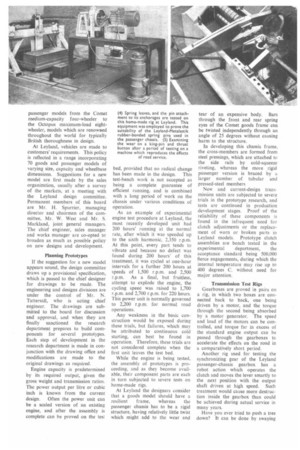
Have you ever tried to push a tree down? It can be done by swaying the trunk backwards and forwards, and adding to the momentum at each stroke. This, in effect, is the method used to test propeller shafts. A & h.p. electric motor, used in conjunction with a heavy flywheel and bob weight, can snap or twist a strong shaft with comparative ease.
On this apparatus, one end of the shaft is secured through its coupling solidly to the bed, whilst the opposite end is bolted to the heavy flywheel, which is supported in bearings so that no load is carried by the shaft. The maximum torque available from the engine, in conjunction with the lowest gear ratio, is calculated and a percentage is added to compensate for shock loading caused by a fierce engagement of the clutch.
Having found the greatest possible torsional load which will be transmitted in actual service, this is then imposed on the shaft in the rig by oscillating the bob weight, the frequency depending on the resistance of the shaft to the load imposed. The bob weight is maintained in motion by the electric motor until fracture occurs.
Wheel hubs and discs are tried on much the same principle. In the first rig, a tyre is held rigidly in a circumferential clamp, and a beam bolted to the wheel disc is oscillated through a bearer and weights to represent the side thrust during fast cornering. A modified structure of this type is employed to prove the material and
machining of the hubs. After these experiments have been completed,
the initial specification of the material may require to be altered or, in other cases, the radius blending two lands may have to be changed. A massive machine is employed for measuring the friction required to turn the king-pin on its thrust button and the rate of wear of the two complementary parts. Experience gained during extensive trials has resulted in lighter steering and less wear.
There are jigs and fixtures for test ing the steering, brakes, suspension, axles, electrical equipment and all other components of the chassis far beyond the limits encountered in normal service. When all parts have
passed shop tests and been finally approved, the first six prototypes are
assembled for road testing.
Usually, two articulated tractors, tippers and long-wheelbase load car
riers comprise the first models, which are driven ruthlessly on endurance trials. Drivers are instructed not to
abuse the vehicles unnecessarily, but to drive them hard.
The long-wheelbase models are usually allocated, one to longdistance haulage with a full load and operating with a double shift of drivers, and the second possibly to work over a course requiring frequent gear changes. Both tractors undergo similar endurance tests, but for the tippers the work is somewhat different. They work in a quarry on short hauls and for part of the time, operate with a reduced load. It has been found that chassis wear is often accelerated by part-load operation, especially where the work entails a fair measure of off-the-road running.
Load carried, distance covered, fuel and oil used, adjustments, failures and other relevant details are carefully recorded, and modifications to the chassis are introduced as re
quired. When these trials have proved the vehicle to be satisfactory, the engine governed speed may be raised by 10 per cent, or more, to increase the rate of wear. Further testing is done over the pave and washboard sections of the Motor Industry Research Association's track at Nuneaton.
Trials are continued after the prototypes have been proved and put into production, and from this stage improvements may be made and introduced as modifications, or, if any major development be required. a Mark II model may be introduced.