


A VAN TILT TO PERMIT MECHANICAL LOADING.
Page 32
If you've noticed an error in this article please click here to report it so we can fix it.
A Résumé of Recently Published Patent Specifications.
THE full advantage of loading by means of cranes or runways has always been much restricted where tilt corers were used to protect the contents/ of a van. A compromise has been made, especially in the northern railway, vans, by providing a few hoops near the•driver's seat, and attaching thereto a
tarpaulin which can be pulled forward. This allows goods to be placed in position by a crane, after which the tarpaulin is pulled rearwards to protect the goods.
Other attemirts have been made in the form of a permanent tilt the top of which has been provided with flaps that would lift up to enable a 'crane to operate. Neither of these plans has, however, proved entirely satisfactory. The specification of J. H. Sparkshatt, No. 248,949, appears to show a tilt that will meet every need of a van that can be loaded by a crane, and at the same time afford a means of protecting goods from weather and theft, whilst it can easily be operated by one man. It will be seen that the tilt is supported by groeves formed in the permanent cab which covers the driver's seat, and that it can be slid forward to enable goods to be located by means of cranes or other arrangements, and returned to its original position for travelling. Locking devices and a rack and pinion could easily be added' if required. The idea (the practical application of which we dealt with a few months ago) appears to us to be a very practicable one, and we shall be glad to hear more of this invention.
A Suggestion in Connection with Covered Tops.
A FORM of vehicle top cover par
ticularly adapted to use in tramcars is described in the specification of W. E. Fowler, No. 249,014, which the inventor points out might, with some modifications, be adopted for use on motor vehicles such as buses or chars 6.-bancs. Although, as shown, it is essentially intended for tram use, there appears to be enough merit in it to set one thinking of possibilities of its adap
tation to other classes of vehicle. If employed for use on a vehicle which has no trolley-pole pedestal, as shown, the structure might cover the entire width of the vehicle.
The construction is made fairly plain by the drawings, which show a structure consisting of rails and standards.
C48
'Along these rails slide the fixings of the cross-bars which support the covering, which might consist of any light: material, hinged together and capable of folding up as shown in the small View.
No means is described of supporting the centres of the folding members when they lie in a horizontal position, but such supports could easily be designed so that they would not sag. Side protection is shown, but it is not at all clear how these side plates can be attached to a member which hinges in halves as shown in the various views. Perhaps the inventor or some other person might use the main idea, and from it evolve a solution of the problem of the open and covered bus.
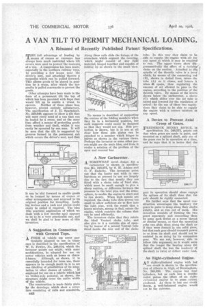
A New Carburetter.
A SOMEWHAT novel design for a
carburetter is shown in specification Wo. 243,875, by S. H. Adams and C. F. Enderby. The inventors point out that the faults met with in carburetters at present in use are largely due to the fact that mostly they are fitted with a choke tube of fixed size, which must be small enough to give a sharp suction, or difference between the pressure in the inlet pipe and the atmosphere, to enable the engine to start and to run slowly. When high speeds are required, the choke tube then proves too small to allow sufficient air to flow into the inlet pipe, with the result that a heavy mixture, strong in fuel, enters the engine, which restricts the volume that can be used efficiently.
The inventors claim that they retain the ideal Venturi choke tube, and also give to it a variable size of opening by means of a second Venturi tube fitted inside the rear end of the choke
tube. In this way they claim to be able to supply the .engine with, air for any speed at which it may be required to run. The upper views show diagrammatically the effect of a variabbe choke on the suction. Attached to the ? spindle of the throttle valve is a levet' • which, by means of the connecting rod (B), shown in dotted lines, raises the tube (A) as it closes, and lowers A when Aft opens, thus regulating the amount of air allowed to pass to the engine, according to the position of the throttle valve. By means of the levers shown below the carburetter, a sleeve (C) which slides over the jet tube is raised and lowered for the regulation of petrol; by the use of these two regulations they claim to be able to supply the engine with a correct mixture at any speed.
A Device to Prevent Axial Creep of Gears.
FREDERICK HENRY ROYCE, in specification No. 248,573, points out that when gears are made in pairs, and mounted on a splined shaft, only one of the gears can be in operation at a time, and he says that it is better that the gear in operation should alone engage the splines .of its shaft than that the pair should be rigidly connected.
He further says that the usual construction encourages the tendency for gears in pairs to creep along their Shafts axially, and so run out 'of mesh. His invention consists of forming the two gears separately and connecting them by some such device as a screw thread or similar means, so that the operating yoke can slide them along the shaft as if they were formed in one solid piece, but that each gear should transmit power to or from its shaft and should 'not be assisted in so doing by its companion gear. We are not, however, able to follow this argument, as it would seem that the longer the bearing along the splined shaft the less the tendency of the shaft to twist or deflect under load.
An Eight-cylindered EnAine.
AN eight-cylindered engine with but
one crank is shown in the specification of Alberto A. Gigli, of Birmingham, No. 248,556, The engine has four cylinders, but as each has a doubleended piston the effect of • an eight7. cylindered engine is to some extent produced. As there is but one crank throw, a well-balanced engine would not be the outcome.