


Universal Trailer Chassis
Page 82
If you've noticed an error in this article please click here to report it so we can fix it.
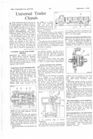
ASEMI-TRA1LER chassis that can be raised, lowered or tipped is shown in patents,No,e869,641. Its primary purpose is for loading containers on or off rail trucks, hut it can also be used with a standard body attached. (Rheinstahl Siegener Eisenbahnbedarf A.E., DreisTiffenbach. Siegen, Westfalen, Germany.)
The drawing shows the vehicle coupled to its two-wheeled tractive unit with a body of normal shape carried on its frame. The •chief feature is that the wheels are attached to the frame (11 through bell-cranks (2) at front and rear. These can be swung by hydraulic rams (3) to any desired angle, thus lifting the body. This is useful in matching up to CONTROL VALVE FOR POWER BRAKES
PATENT No. 868,081 comes from Robert Bosch, G.m.b.H., StuttgartW., Germany, and shows a valve for controlling compressed air for braking. Only one valve is used, but it controls both the timing and the intensity of two separate brake systems.
INJECTION PUMP DISTRIBUTOR
A DISTRIBUTOR type of fuel inject-1 tion pump is shown in patent No. 870,341. The main feature is the method of control, by which the pressure of the fuel increases with the quantity discharged. (G. Green and G. Fox, 100 Wells Road, Malvern, Worcs.)
Referring to the drawing, a multiplunger pump (1) of the cam-ring type delivers fuel under pressure to an
annulus (2) via a port (3). A rotor (4) which can also slide endways, revolves in the central bore.
High-pressure fuel from the pump is distributed to the various fuel outlets (5) as the rotor turns. The quantity is regulated by endwise movement of the rotor by forks (6) actuated by the accelerator pedal. The sliding movement varies the charge because the cut-away portion (7) is wedge-shaped.
The spring-loaded valve (8) governs the B20 the height of a railway wagon. The hydraulic rams also form the suspension units, and for this purpose an air reservoir is incorporated to function as a spring.
An additional feature is the provision of a roller-bearing turntable (4). When a container has been raised to the correct height, the turntable is swung through 90 deg. ana the container rolled off on rails (5).
The body can also be tipped to the rear about pivots (6) by means of an hydraulic ram (not shown). A hinged wheel (7) is carried by the tractor to support it when the trailer is removed.
fuel delivery pressure. As the rotor is moved to the right, the spring (9) is compressed, and this raises the maximum delivery pressure when the quantity of fuel is increased.
A second scheme shows the pump modified to prevent fuel being delivered in excess of engine-torque requirements.
SPARK IGNITED OIL ENGINE
'.ATENT No. 870,255 shows a supercharged diesel engine employing a sparking plug to ensure ignition at idling speed, when the mixture is weak. (Hanomag A.G., Hamelner Strasse 8, Hanover, Germany.) Referring to the drawing, the injector (1) is located in a pre-combustion chamber which also houses the sparking plug (2). The nozzle has a number of jets, giving a spray as shown at 3. The jets are so arranged that at low engine speeds the part of the spray striking the wall of the combustion chamber in the vicinity of the plug is greater than that entering the cylinder and can be ignited by the sparking plug to initiate combustion.
Scavenging is of the reversed-loop type, the compressed-air charge entering the cylinder via a port (4) at the bottom. As it sweeps upwards, it encounters the downward spray of fuel (5) and is thus able to mix thoroughly.
FRICTION-DAMPED DIFFERENTIAL
PATENT No. 869,103 shows a differential gear modified so that the differential action is frictionally damped by clutches, which are loaded by the torque transmitted, The object is to reduce the
tendency for lost traction if one wheel slips. (Eaton Manufacturing Co., 739 East 140th Street, Cleveland, Ohio. U.S.A.) Multi-plate friction clutches as shown at (I) are located between the half-shaft bevel gears and the casing (2). Alternate plates are splined to the casing and the bevel-gear hubs.
As these clutches are at the thrust faces of the bevels, the greater the transmitted torque, the tighter the plates are pressed together. This limits the freedom of the differential and, under heavy load conditions, a semi-solid drive is transmitted to both wheels.
SQUARE-ENDED VALVE SPRINGS A VALVE-SPRING made so that eacl. of its end coils is a flat ring, squarc with the axis, before the start of th4 helix forms the subject of patent No 870,368. (Ford Motor Co., Ltd., 81 Regent Street. London, W.I.) NON-DISTORTING CAB MOUNTINC PATENT No. 866,255 shows a methoc of mounting the driver's cab so tha it is not stressed by twisting of the frame It is secured only to the frame under th, centre of gravity, rubber buffers bein used elsewhere. The patent comes fron Daimler-Benz A.G., Stuttgart-Unter turkheim, Germany.