


A New Design
Page 36
If you've noticed an error in this article please click here to report it so we can fix it.
of Rotary Engine
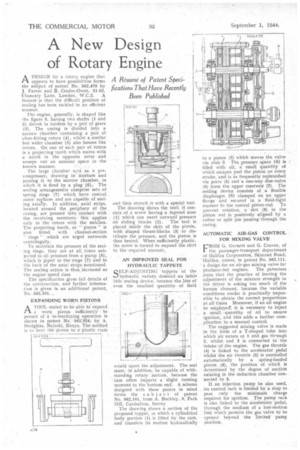
ADESIGN for a rotary engine that appears to have possibilities forms the subject of patent No. 562,478 by J. Fareso and B. Cradoc-Owen, 51-52, Chancery Lane, London, W.C.2. A feature is that the difficult problem of sealing has been tackled in an efficient ma nner.
The engine, generally, is shaped like the figure 8, having two shafts (1 and 2) clriveii in tandem by a pair of gears (3). The casing is divided into a narrow chamber containing a pair of close-fitting rotors (4), whilst a similar but wider chamber (5) also houses like rotors. On one of each pair of rotors is a projecting tooth which mates with a notch in the opposite rotor and sweeps out an annular space in the known manner.
The large chamber acts as a pre. compressor, drawing in mixture and passing it to the narrow chamber, in which it is fired by a plug (6), The sealing arrangements comprise sets of spring rings (7) which have conical outer surfaces and are capable of sealing axially. In addition, axial strips, located around the periphery of the casing, are pressed into, contact with the revolving members; this applies only to the rotors with the notches. The projecting tooth, or " piston '' is also fitted with channel-section " rings" which are urged outwards centrifugally. To maintain the pressure of the sealing rings, they are at all times subjected to oil pressure from a pump (8), which is piped to the rings (7) and to the back of the axial strips mentioned. The sealing action is thus, increased as the engine speed rises The specification gives full details of the construction, and further information is given in an additional patent, No. 562,301..
EXPANDING WORN PISTONS
ATOOL stated to be able to expand a worn piston sufficiently to permit of a re-machining operation is shown in patent No. -562,324, by A. Floclgkiss, Nairobi, Kenya. The method is to heat the pkton to a plastic r.tate :i62. 324
and then stretch it with a special tool. The drawing shows the tool; it consists of a screw having a tapered nose (1) which can exert outward pressure on sliding blocks (2). The tool is placed inside the skirt of the pistOn, with shaped thrust-blocks (3) to distribute the pressure, and the piston is then heated. When sufficiently plastic, the screw is turned to expand the skirt to the required amount, AN IMPROVED SEAL FOR HYDRAULIC TAPPETS
SELF-ADJUSTING tappets of the hydraulic variety demand an infale lible sealing device, because the loss of even the smallest quantity of fluid would upset the adjustment. The seal must, in addition, be capable of withstanding rotary motion, because the cam often imparts a slight turning moment to the bottom end. A scheme designed with these points in mind forms the s ubject of patent No. 562,101, from A. Buckley, 9, Park Hill, Carshalton, Surrey
The drawing shows a section of the proposed tappet, in which a cylindrical body poition (1) is lifted by the cam, and transfers its motion hydraulically to a piston (2) which moves the valve via stub 3 The pressure space (4) is filled with oil, a small quantity of which escapes past the piston on every stroke, and is as frequently replenished via ports (5) and a one-way disc-valve (6) from the upper reservoir (7). The sealing device consists of a flexible diaphragm (8) clamped on an upper flange and secured in a fluid-tight manner to the central piston-rod. To prevent rotation, a slot (9) in the piston rod is positively aligned by a cotter or split pin passing through the casing.
AUTOMATIC AIR-GAS CONTROL FOR MIXING VALVE
FROM G. Garnett and G. Craven, of the passenger-transport department of FIallfax Corporation, Skircoat Road, Halifax, comes, in patent No. 562,111, a design for an air-gas mixing valve for producer-fed engines. The patentees state that the practice of leaving the adjustment of the mixture strength to the driver is asking too much of the humanelement, because the variable conditions render it practically impossible to obtain the correct proportions at all times Moreover, if an oil engine be erriployedfr, it is necessary to inject a small • quantity of oil to ensure ignition, and this adds a further complication to a manual control.
The suggested mixing valve is made in the form of a T-shaped tube into which air enters at 1 and gas th-ough 2, whilst end 3 is connected to the intake of the engine. The gas throttle (4) is linked to the accelerator pedal whilst the air throttle (5) is controlled automatically by a spring-loaded piston (6), the position of which is determined by the degree of suction existing in the induction chamber connected to 3.
If an injection pump be also used, its control rack is limited by a stop to pass only the minimum charge required for ignition. The pump rack is also linked to the acceleratot pedal, through the medium of a lost-motion link which permits the gas valve to be opened beyond the limited pump position.