


Why Not Disc
Page 28
If you've noticed an error in this article please click here to report it so we can fix it.
Brakes ?
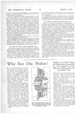
IT is a surprising fact that the disci type brake is so little used, when it is considered that the same construction has been so successfully applied' to clutches, and it is interesting to note that a recently published patent (No. 510,037), describing such a brake, comes from a specialist in clutch design, Borg and Beck Co., Ltd., Brock House, Laugh= Street, London, W. 1. The co-patentee, furthermore, is an equally well-known figure, namely, Captain G. E. T. Eyston. The design is said to be suitable for the heaviest vehicles including lorries, railway wagons and military tanks. The drawing—representing an application of the scheme to a machine of the last named type—shows a section of the brake, which in its essentials closely follows clutch practice. The rotating member, attached to the axle (9), consists of a disc (10) faced with the usual friction material, whilst the outer casing is stationary and is bolted to the back plate (8). The working pressure is created hydraulically by means of a number of pistons (2) spaced around the casing and pressing against the plate (1) duringoperation. The pistons are connected to the source of hydraulic pressfire by annulus 7.
As a standby, a second method of operation is provided. This comprises
a26 a free sleeve (5) which can be partially rotated by a pull-rod attached to the
arm (6). Three studs (3) on the sleeve slide in helical slots in the outer member (4), and so produce an endpressure on the plate (I).
One important object of the patentees in developing a brake of this type was to take advantage of the opportunities afforded for improved operating gear.
Each piston in the fluid cylinders is provided with a spherically ended projection which bears upon a shallow recess in the back face of the non
rotating pressure plate. To allow this to have free axial movement when under toad, torque reaction is taken by two or more rollers, radially disposed, and mounted on pins projecting from lugs on the periphery of the pressure plate. These work in grooves in the outer casing.
Cooling is promoted by slots formed in the rim of the disc, between the annular friction-material facings. These have a fan effect and provision is made for the escape of air by apertures in the periphery of the casing.