


A NEW FORM OF CYLINDER HEAD.
Page 68
If you've noticed an error in this article please click here to report it so we can fix it.
A Resume of Recrently Published Patent Specifications.
MITE form of cylinder head shown in the specification No. 287,258 of Albert George Elliott is said to produce turbulence and to allow a higher degree
of compression to be employed without the usual disadvantages of -a very high compression. Several forms of combustion chamber are shown ; these all tend to provide a chamber which, for the purpose of producing turbulence, is less in aection than the bore of the cylinder, so that the combustion chamber is not in symmetrical continuation with the wall of the cylinder. TWo sparking plugs are shown, but no claim is made for their use.'
Maintaining the Water Level in Radiators.
Tim invention described in patent
specification No. 286,388, by Raymond Hugh Rose, of Manchester, is for a means :for maintaining the water level in radiators and keeping a supply of water in a replenishing tank so that the trouble of replenishing during a journey may be avoided. To carry out this 'plan, it is necessary that the filler cap should be an air-tight fit on its
seating. The overflow pipe extends above the level of the cap and is enclosed by a disc which is provided with glass BO that the height of the water in the chamber can be seen by the driver and thus acts as 1111 indication that the proper quantity of water is in the radiator.
When the temperature of the water in the. radiator rises to the working height expansion takes place and an overflow follows, but not in the usual way where the contents are wasted, the water, instead, being stored in the replenishing tank. When the radiator cools down, a partial vacuum is formed,
-which sucks up water from the replenishing tank and so replaces any that may have been lost through the making of steam, as steam which has to find its way through the water in the replenishing tank becomes condensed. A space is Provided between the overflow pipe and the aperture in the filler cap, through which the water can rise to find its way 'down the overflow pipe
provided. '
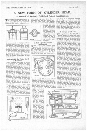
A Self-adjusting Brake Mechanism. ,
MANY devices have recently been patented for the automatic adjustment of brakes, but that described in the specification No. 287,033 of George Henry Enderby appears to be one of the simplest we have seen. The illustration is so clear that little descrip lion is needed. The fulcrum ends of the shoes are pivoted to crank pins projecting from the disc shown, the other ends of the shoes being operated by the usual cam device. Attached to the spindle which carries the cranks is a wheel with ratchet teeth cut on a part The ratchet teeth are so arranged that the play of the lever, which carries the pawl, is not sufficient to make the pawl drop at the end of a tooth. In other words, the length of each tooth is less than the normal travel of the pawl, but when, through wear of the fabric, the cam lever moves more to the
right than it is originally intended to, it slips a tooth and on its return to the " off " position takes with it the cranks, thus widening the distance between the fulcrum ends of the shoes, by so doing effecting an adjustment. A detent pawl holds the ratchet wheel from following the lever on its return to the " off " position.
A Change-speed Gear.
THE specification No. 287,386 of rnold Seidel, of Berlin, like many pateut specifications of to-day, does not explain the object of the invention, but we take it that the' main idea is the prevention of damage to gear teeth while changing from top gear to the
highest of the indirect gears. The Fhaft on the left is that leading from the engine' and is provided with the usual pinion' for engagement with the gear on the layshaft and with dogs for coupling it to the driven shaft. The member A, which carries the dogs for top-gear engagement, slides along splines on the driven shaft and is controlled by the yoke attached to the extensionof O. The member B is free to -revolve on A, and is controlled' by the yoke (0); so that both A and B slide together. Teeth are formed on the outside of II, so that they can engage with the gear on the layshaft which forms the highest of the indirect gears and B is provided with internal splines formed on the splined sleeve which surrounds the driven shaft.
The engagements of the first and second gears are as usual, but the engagement of the third gear is as follows :—As the yoke slides to the right it causes the gear teeth to engage, but, as B is free to revolve, there can be no damage to its teeth. A further movement, after the teeth have engaged, brings the internal splines of B in engagement with the external splines of the sleeve on the driven shaft, and so forms a coupling. Unless we are mistaken, we have seen something very like this in the Dux gearbox, and again in certain of the early models of the Commer car.