


The Multipede.
Page 5
Page 6
Page 7
If you've noticed an error in this article please click here to report it so we can fix it.
An All-British " Caterpillar " in Design and Construction, Emanating from that Notable Concern Clayton and Shuttleworth, Ltd.
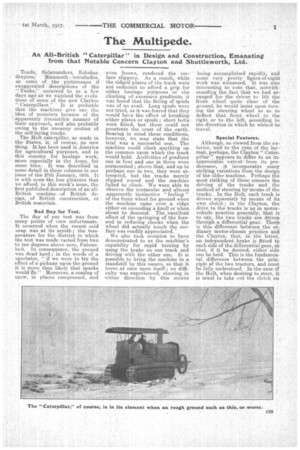
Toads, Salamanders, Echidna dragons, Mammoth tetrahedra, as some of the picturesque if exaggerated descriptions of the " Tanks," occurred to us a few days ago as we watched the evoli. tions of some of the new Clayton " Caterpillars." It is probable that the machines give one the idea of monsters because of the apparently irresistible manner of their approach, and also probably owing to the uncanny motion of the self-laying tracks.
The Holt caterpillar, as made in the States, is, of course, no new thing. It. has been used in America for agricultural purposes, and in this country for haulage work, more especially in the Army, for some time. It Was described in some detail in these columns in our issue of the 27th January, 19113. It is with nonetheless pleasure that we afford, in this week's issue, the first published description of an allBritish machine—of British design, of British construction, 01 British materials.
Bad Day for Test.
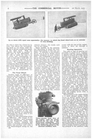
The day of our test was from many points of view unfortunate. It occurred when the recent cold snap was at its zenith ; the temperature for the district in which the test was made varied from two to ten degrees above zero, Fahrenheit. In consequence, the ground was dead hard ; in the words of a spectator, "if we were to try the effect of a pickaxe upon the ground it is more than likely that sparks would fly." Moreover, a coating of snow, in places compressed, and even frozen, rendered • the surface slippery. As a result, while the ridged plates of the track were not sufficient to afford a grip for either haulage purposes or the climbing of excessive gradients, it was found that the fitting of spuds was of no avail. Long spuds were not tried, as it was feared that they would have the effect of breaking either plates or spuds ; short bolts were fitted, but these could not penetrate the crust of the earth. _Bearing in mind these conditions, however, we may state that the trial was a successful one. The machine could climb anything on the common upon which the track would hold: Acclivities of gradient one in four and one in three were surmounted ; above that, and up to perhaps one in two, they were attempted, but the tracks merely slipped round and the machine failed to climb. We were able to observe the tentacular and almost apparently instinctive " feeling " of the front. wheel for ground when the mac'hine came over a ridge either on ascending a knoll or when about to descend. The excellent effect of the springing of the foreend in reducing shocks when the wheel did actually touch the surface was readily appreciated..
We also took occasion to have demonstrated to us the machine's capability for rapid turning by using the brake on one track and driving with the .other one. It is possible to bring the machine to a standstill by this means, so that it turns at once upon itself ; no difficulty was experienced, steering in either direction by this means being accomplished rapidly, and some very pretty figure-of-eight work was witnessed. It was also interesting to note that, notwithstanding the fact that we had arranged for the driver to lift the front wheelquite clear of the ground, he would insist upon turning the steering wheel so as to deflect that front wheel to the right or to the left, according to the direction in which he wished to travel.
Special Features.
Although, as viewed from the exterior, and to the eyes of the layman, perhaps, the Clayton" Caterpillar'! appears to differ to an inappreciable extent from its predecessor, it incorporates many striking variations from the design of the older machine. Perhaps the most striking of these concern the driving of the tracks • and the method of steering by' means of the tracks.. In the Holt, each track is driven separately by means of its own clutch ; in the Clayton, the drive to the tracks is as in motorvehicle practice generally, that is to say, the two tracks are driven through a differential gear. There is this difference between the ordinary motor-chassis practice and the Clayton, that, in the latter, an independent brake is fitted to each side of the differential gear . sb that, if it be desired, either side can be held. This is the fundamental difference between the principle of the two tractors, and must be fully understood. In the case of the Holt, when desiring to steer, it is usual to take out the clutch, on
the side to which the vehicle has to turn ; this allows the corresponding track to run freely while the Vehicle is driven round it by means of the lther track. With the Clayton, the brake is applied to that half of the differential on the side to which the turn is to be made, and, consequently, the track on that Side is held still ; the other track then operates to propel the machine in the required direction. To compensate for the multiplying. effect of the differential gear when used in this manner, the first speed, which is invariably used for turning in difficult circumstances, is an exceptionally low
ODO.
The Front Wheel.
Another point of difference as between the Holt and the Clayton relates to the suspension of the front wheel. In the case of the former, this is rigidly attached to the framework. On the Clayton, the front wheel is carried in a speciallyarranged bracket on a pivot between the ends of a long, pressedsteel pair of arms. These arms carry from their rear ends a segment of a large cog wheel disposed in a vertical plane. Into this gears a spur wheel, which itself is controlled by a worm-and-wheel gear, operated by a hand wheel. A floating connection between the spur elevating-wheel and the worm sector allows the front wheel a vertical movement above and below its mid position of some 15 degrees each way. Powerful coil springs tend always to press the road wheel on to the ground. They also have the effect, if the wheel owing to unevenness of surface at any time leaves the ground, of considerably cushioning the shock when it hits the ground once more.
These are the outstanding points of difference. The design of the Clayton embodies : steel pressings for the framework rather than built-up girders, channels and angles ; a complete covering for the engine and gearbox unit, with a neat funnel-shaped casing for the c30 exhaust silencer ; the tracks each run on two chains.
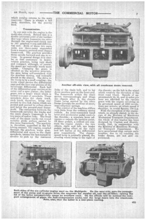
Ii.Space forbids, at the moment, ur describing in' detail the techical construction of this new mahine. It embodies a six-cylinder,.i, in. bore by 6i in. stroke, petrol ngine, designed on. most modern nes. The crankshaft is carried in seven bearings of a special design hich eliminates the necessity for achining within the crankcase of all except the bored holes for crank and camshafts. The lubrication is forced to the big-ends as well as the main bearings, the system embodying a duplex type of filter, designed so that one filter can be removed and cleaned without in any way interfering with the running of the engine. A feature has been made of short, straight oilways, and an excess-pressure valve is also provided, the oil from which flows into a tank. This surplus serves as a supplementary supply of oil for certain minor bearings ; it is not essential, as the lubrication is self-contained and complete apart from this. The engine cooling is by pump-circulated water. A large chain-drivan fan, coalmen surate with the size of the engine, serves to draw air through a radiator.
Starting Apparatus.
Two aids to ease of starting are provided. A small C.A.V. magneto is geared with the starting handle so that it revolves at a high speed and provides current to the plugs through the main magneto distributor. A special arrangement prevents the main magneto from operating during this period, so that there is no risk of a backfire. Immediately the engine is started and the starting handle is released, the small auxiliary magneto ceases to operate. Each cylinder is provided with a hand-controlled combined screw-down and ball halfcompression Valve. It is designed so as to avoid pockets which might serve as receptacles for inert gas, and the ball valve, while allowing of the escape of some of the mixture on a compression stroke, prevents induction of air in the suction_ stroke. The cylinders are separately cast, and fitted with overhead valves, each pair being carried in a separate combustion head, and all operated by long tappets and rocking levers from a single camshaft.
Incorporated in the engine design is a small plunger pump, which serves to .deliver petrol from the main tank at the rear to an auxiliary one which. is placed high so that it affords gravity feed under the most difficult circumstances in respect of gradient. Incidentally, it may be remarked here that in the original design the position of this tank was calculated for a gradient of one in three to one in four. The capability of the machine for ascending steeper hills, we are informed, is one in one (that is to say a slop of 45 degrees has been successfully climbed). This rendered it necessary for a pipe to be fitted above this tank so as to increase the head by more than 1 ft. The petrol pump is of such capacity that a surplus of fuel is always being pumped to the auxiliary tank, which surplus returns to the main reservoir. There is always a full tank, therefore, for the gravity feed.
Transmission.
In one unit with the engine is the multi-disc clutch. Behind this is a double universal joint of the leatiierdisc type which transmits the drive through the engine-and-clutch unit to the gearbox-worm-and-differential unit. Both of these two main units are three-point suspended from a massive pressed-steel chassis framework. The gearbox provides three speeds forward and one in re, verse. In general design it is similar to that customary in heavyvehicle practice, being very short and compact, although, of course, the gears are naturally much more robust. Changing the gears is effected on the selective principle, the gate being self-contained with the gearbox casting, and centrally placed in the chassis. The drive to the worm is by a muff coupling ; the worm wheel carries the differential cage and the four star pinions of the bevel-type differential. Each half of the differential gear carries at its outer end a spur pinion ; the latter gears into a larger wheel which is bolted to a pair of sprockets. These sprockets drive the chain track, each track, therefore, being supported by two link chains which are guided and carried by rollers above and below the pressed-steel framework The connection between the framework carrying the tracks and the main chassis framework is by two pairs of radius links. The front ends of the chain tracks run round suitable guide pulleyscarried by this same framework. The machine is, therefore, propelled in the following manner. The engine, coupled through the gearbox, worm gear, differential and spurs to the chain sprockets, causes the last-named to revolve, to pick up the rearmost
links of the chain belt, and to lay down another pair at the front end. The framework within the chain moves correspondingly and drags the chassis after it, the chassis frame being carried by the other frame through the medium of stout, semi-elliptical springs.
The control of the machine differs very little from the ordinary motor vehicle. An inter-connected hand lever and accelerator pedal controls the throttle ; a separate lever advances or retards the ignition point. Of three pedals, a central one controls the engine clutch ; the two others, right and left, are. brake
• pedals taking effect on the right and left halVes of the differential gear respectively. The changespeed lever is centrally placed, the steering wheel being to the right of the chassis ; on the left is the wheel which controls the elevation of the front road wheel. Speeds of approximately 6, 31, and 1.1miles per hour are afforded by the various gears with the engine revolving at its governed speed of 1000 revolutions per minute, at which speed it develops, in round figures, 100 h.pi
With the exception of the engine which, as already stated, is the de. sign of the Ministry of Munitions Mechanical Transport Department, the whole of this tractor has been designed by Clayton and Shuttle worth, Ltd., in conjunction with the Ministry of Munitions Mechani cal Transport Department. We have ascertained that certain early troubles, due to oil reaching the brake drums, are not now experienced.