


Patents Completed.
Page 20
If you've noticed an error in this article please click here to report it so we can fix it.
Another Decompressor. Method of Mounting Flywheel. Mushroom Valve with Renewable Face.
L. BACIIELOR, No. 72B9, dated 27th March, 1913.—This specification describes a compression-relieving device which has two valves opening in opposite directions. One of these
opens when the pressure in the cylinder is to6 great, and thus relieves the compression, while the other opens inwards to prevent the production of a vacuum in the cylinder. The device is made as a separate fitting, with a stop-cock to render it inoperative when desired. It comprises a hollow poppet valve, which opens outwards from the cylinder, and is pressed down on to its seat by a spring, this spring being sated on a cap nut which covers the valve.
Within the main valve is situated a second poppet valve, opening inwards, and haying its seating upon the inner end. of the former. The smaller valve is held on to its seat by a comparatively weak spring, so that. it. can yeadily open under atmospheric pressure.
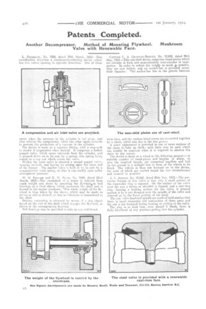
W. 0. SPILLER and E. M. ELM, No. 7000, dated 22nd March, 1913.—The crankshaft of a motor is relieved from much weight and stress by mounting the flywheelkon ball bearings on a fixed sleeve, which surrounds tio shaft and is housed in the engine crankcase. %The whole weight of the flywheel is thus taken by the sleeve, which may be made as strong or -stiff as desired, so that no vibration is transmitted to the shaft.
• Driving connection is ohttpined by means of a dog clutch keyed on the end of the shaft which enoges the flywheel, as shown in the accompanying drawing.
Ball bearings may be provided to take up an end thrust. CAPTAIN C. A. CRAW LEY-BOEVEY, No. 12,242, dated 26th May, 1913.—This non-skid device comprises tread-pieces which are circular in form and approximately semi-circular in crosssection. In order to reduce the weight as much 9,,s passible, they are cast hollow, an an anchor-bar is provided acres:, their diameter. This anchor-bar lies in the groove between
twin tires, and the various tread-nieces are connected together by a chain, which also lies in the tire groove.
A screw adjustment is provided in one or more sections of the chain to-take up slack; split links may be used which can readily be removed when it is required to shorten the chain to any extent.
The device is fixed on a wheel in the following manner :—A suitable number of tread-pieces and lengths of ehain, to give the required length, are connected together and laid on the ground in a straight line in front of the wheels to be fitted. The vehicle is then run forward on to the device, the ends of which are carried round the tire circumference and secured in position.
J. C. JENSEN, No. 12,662, dated 30th May, 1913.—The particular feature of this valve is that only a small portion of the renewable ring is exposed. On the surface of the valve next the scat a facing or shoulder is formed, and a cast-iron ring, forming a hearing surface for the valve, is pressed against it by a nut dropped over the spindle of the valve and screwed on to the lower portion of the head.
The nut, valve head and spindle are made of mild steel so that there is-equal expansion and contraction of these parts and the nut is not loosened during heating or cooling of the valve. The ring is so held that, even should it break, there is little likelihood of any portions getting into the cylinder.