


A New Design of Ricardo Head
Page 52
If you've noticed an error in this article please click here to report it so we can fix it.
A Resume' of Recently Published Patent Specifications, Copies of which, Price is., can be Obtained from the Patent Office
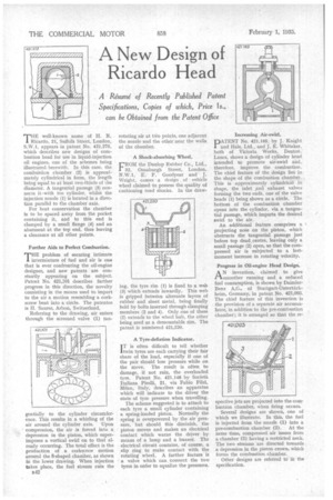
THE well-known name of H. R. Ricardo, 21, Suffolk Street, London, S.W.1, appears in patent No. 421,275, which describes new designs of combustion head for use in liquid-injection oil engines, one of the schemes being illustrated herewith, In this case, the combustion chamber (2) is approximately cylindrical in form, the length being equal to at least two-thirds of the diameter. A tangential passage (3) connects it-with the cylinder, whilst the injection nozzle (1) is located in a direction parallel to the chamber axis.
For heat conservation the chamber is to be spaced away from the pocket containing it, and to this end is clamped by a small flange (4) and an abutment at the top end, thus leaving a clearance at all other points.
Further Aids to Perfect Combustion.
T"problem of securing intimate intermixture of fuel and air is one that is ever confronting the oil-engine designer, and new patents are constantly appearing on the subject. Patent No. 421,101 describes further progress in this direction, the novelty consisting in the means used to impart to the air a motion resembling a corkscrew bent into a circle. The patentee is H. Saurer, Arbon, Switzerland.
Referring to the drawing, air enters through the screened valve (1) tan
gentially to the cylinder circumference. This results in a whirling of the air around the cylinder axis. Upon ' compression, the air is forced into a depression in the piston, which superimposes a vertical swirl on to that already occurring. The total effect is the production of a corkscrew motion around the 8-shaped chamber, as shown in the lower drawing. When injection takes place, the fuel stream cuts the B42 rotating air at two points, one adjacent the nozzle and the other near the walls of the chamber.
A Shock-absorbing Wheel.
LROM the Dunlop Rubber Co., Ltd.,
32, Osnaburgh Street, London, N.W.1, E. F. Goodyear and J. Wright, comes a design of vehicle wheel claimed to possess the quality of cushioning road shocks. In the draw ing, the tyre rim (1) is fixed to a wali (3) which extends inwardly. This web is gripped between alternate layers of rubber and sheet metal, being finally held by bolts inserted through clamping members (2 and 4). Only one of these (2) extends to the wheel huh, the other being used as a demountable rim. The patent is numbered 421,220.
A Tyre-deflation Indicator.
I T is often difficult to tell whether twin tyres are each carrying their fair share of the load, especially if one of the pair should lose pressure while on the move. The result is often to damage, if not ruin, the overloaded tyre. Patent No. 421,148 by Societa Ithliana Pirelli, 21, via Fabio Filzi, Milan, Italy, describes an apparatus which will indicate to the driver the state of tyre pressure when travelling.
The scheme suggested is to attach to each tyre a small cylinder containing a spring-loaded piston. Normally the spring is overpowered by the air pressure, but should this diminish, the piston moves and makes an electrical contact which warns the driver by means of a lamp and a buzzer, The electrical circuit contains, of course, a slip ring to make contact with the rotating wheel. A further feature is a valve which can connect the two tyres in order to equalize the pressures. Increasing Air-swirl.
DATRNT No. 421,165, by J. Knight J. and Hale, Ltd., and J. E. Whitaker, both of Victoria Works, Denton, Lanes, shows a design of cylinder head intended to promote air-swirl and, therefore, improve the combustion. The chief feature of the design lies in the shape of the combustion chamber. This is approximately cylindrical in shape, the inlet and exhaust valves forming the two ends, one of the valve heads (1) being shown as a circle. The bottom of the combustion chamber opens into the cylinder, via a tangential passage, which imparts the desired swirl to the air.
An additional feature comprises a projecting nose on the piston, which obstructs the tangential passage just before top deadsentre, leaving only a small passage (2) open, so that the compressed air is subjected to a lastmoment increase in rotating velocity.
Progress in OH-engine Head Design.
AN invention, claimed to give smoother running and a reduced fuel consumption, is shown by DaimlerBenz A.G., of Stuttgart-Untertfirkheim, Germany, in patent No. 421,093. The chief feature of this invention is the provision of a separate air accumulator, in addition to the pre-combustion chamber ; it is arranged so that the re
spective jets are projected into the combustion chamber, when firing occurs.
Several designs are shown, one of which we illustrate. In this, the fuel is injected from the nozzle (1) into a pre-combustion chamber (2). At the same time, compressed air issues from a chamber (3) having a restricted neck. The two streams are directed towards a depression in the piston crown, which forms the combustion chamber.
Other designs are referred to in the specification.