


L.G.O.C.'s GAS EQUIPMENT.
Page 8
Page 9
If you've noticed an error in this article please click here to report it so we can fix it.
Combined Pressure and Flexible Holder System : Completely Automatic :n Action. Vehicle Lighting Included.
"THE MAN IN THE STREET who, advised by his morning paper that his favourite vehicle, a London General Omnibus, was to run on gag, and who•has been on the lookout each day for the first gas-bag
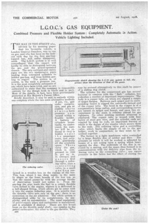
, topped bus, will suffer disappointment.The L.G.O. system is so well camouflaged that the expert will hardly be able to distinguish between the gas and the petrol-operated chassis. The only outward and visible . signs arethe two unobtrusive pipes leading from concealed cylinders to hidden gas-bag, and from hidden gasbag to engine. The system is, of course, in the main a pressure one. It is the most completely automatic of any which have been tried, and we are authorized to state that the company is responsible entirely for the design both in whole and in part. Most of the details, in fact, have been provisionally protected at His Majesty's Patent Office.
Briefly described, it may be said to embody Within one complete whole the two main alternative methods if use, viz., gas under compression_, and gas at slightly abo ve atmospheric pressure c o ntabled within a flexible holder. Abattery of cylinders (eventually, we understand, the number • will be reduced to two) is hidden under t h e passenger seats, and occupies practically all the available space. T hes e carry the gas, which is compressed to 1000 lb. per sq. in. It emerges and passes first through a reducing-valve, then a controlling valve, to a small
gas-bag contained in a wooden box on the canopy of the bus. This box, about S ins, deep inside, is the same fin shape as the front boards of the bus' top, so that the casual passer-by with the average faculty of observation would not notice it. From the gas-bag the pipe leads the fuel to a rotary throttle valve bolted to the engine, whence it is delivered to a bell-shaped fitting, which allows air to enter with it into the engine induction pipe. It is notable that the throttle valve acts only on the gas there is no restriction on the air whatever. The whole system is distinguished alike by its completeness, its simplicity, and its automaticity. The usual equipment of petrol-supply pipes and carburetter is Maintained, and is available if desired. There are two levers loose on the throttle pedal shaft; one couples to the petrol carburetter. the other to the gas throttle. They The reducing valve.
may be secured alternatively to this shaft' by means of a sliding dog clutch-.
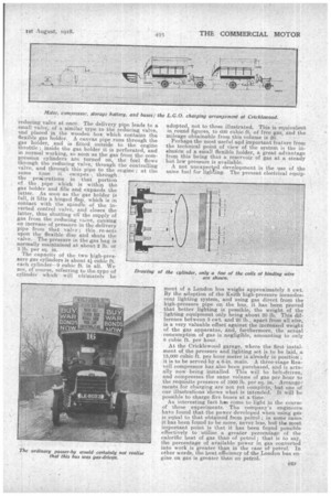
The cylinder for the compressed gas has several features in common with the " Safe" cylinder, but embodies a number of important improvements. The body is a copper tube, on which are slipped a couple of spigot flanges. Between each spigot and its corresponding faucet is nipped the outwardly-turned end of the copper tube. The bend in the copper is of a. comparatively large radius, and corresponding ,curves are turned on spigot and faucet, and upon this circumstance in the main is reliance placed for gas tightness. . No ether jointing medium whatever is employed. The copper tube is wound with four layers of steel gun wire, and the cylinder ends are coupled by long tie rods, an important feature of which is the design of the nipples which secure them to the ends. The reducing valve and a controlling • valve, -which limits the supply of air to the gas holder, work in conjunction, so they must be described together. The former is a light mushroom valve controlled by a large flexible disc 'of rubber and fibre. The pressure at which it will be worked is adjusted by means of a nut acting upon a spring which bears against the disc. The Underside of the disc is enclosed by a casting, and the space thus formed is in communication with the delivery pipe from the reducing valve to the controlling valve ; any excess p Tssure in the latter has the effect of closing the reducing valve at once. The delivery pipe leads to a small valve, of a similar type to the reducing valve, gas holder, and is fitted outside to the engine throttle ; inside the gas holder it is perforated, and. and placed in the wooden box which contains the flexible gas holder. A canvas pipe runs through the
in normal working, so soon as the gas from the compression cylinders are turned on' the fuel flows through the reducing valve, through the controlling' gas from the reducing vaive, causing valve, and through this pipe to the engine ; at the gas holder and fills and expands the the pe-riorations in that portion of the pipe which is within the contact with the spindle of the inlatter, thus shutting off the supply. of an increase of pressure in the delivery pipe from that valve ; this re-acts latter. As soon as the gas holder is verted control valve, and closes the same time it escapes \ through full, it lifts a hinged flap, which is in upon the flexible disc and shuts the valve. The pressure in the gas bag is normally maintained at about 2 lb. or 3 lb. per sq. in. The capacity of the two high-pressure gas cylinders is about 4' cubic ft. each cylinder-9 cubic ft. in all. We are, of course, referring to the.type of Drawing cylinder which will ultimately be adopted, not to those illustrated. This is equivalent in round figures, to 600 cubic ft. of free gas, and the mileage obtainable from this volume is 20.
Perhaps the most useful and important feature from the technical point of view of the system is the inelusion of a small flexible holder, a great advantage from this being that a reservoir of gas at a steady but low pressure is available.
A not unexpected development is the use of the same fuel for lighting. The present electrical equip
ment of a London bus weighs approximately 3 cwt. By the adoption of the Keithiiigh-pressure incandescent lighting system, and using gas direct from the high-pressure pipe on the bus, it has been proved that better lighting is possible, the weight of the lighting equipment only being about 20 lb. This difference between 3 cwt. and 20 lb., apart from all else, is a very valuable offset against the increased weight of the gas apparatus, and, furthermore, the actual consumption of gas is negligible, amounting to only 8 cubic ft. per hour.
• At the Cricklewood garage, where the first instalment of the pressure and lighting set is ,to be laid, a 15,000 cubic ft. per hour meter is already in position ; it is to be served-by a 6-in. main. A three-stage Reayell compressor has also been purchased, and is actually now being installed. This will be belt-driven, and compresses the same volume of gas per hour to the requisite pressure of 1000 lb. per sq. in. Arrange: ments for charging are not yet complete, but one of our illustrations 'shows what is intended. It will be possible to charge five buses at a time.
An interesting fact hale come to light in the course of these experiments. The company's. engineersha,ve found that the power developed when using gas is equal to that obtained from petrol ; in some cases it has been found to be more, never less, but the most important point is that it has been found possible effectively to 'utilise a greater percentage of the calorific heat of gas than of petrol that is to say, the percentage of available power in gas converted into work is greater than in the case of petrol. In other words, the heat efficiency of the London bus engine on gas isv greater than on petrol.