


Patents Completed.
Page 26
If you've noticed an error in this article please click here to report it so we can fix it.
MOTOR VEHICLES. —Pieper. —No. 16,E7ff, dated 4th July, 1906.—This invention relates to motor road vehicles in
which two electro-mechanical groups are arranged to work in series parallel with an accumulator, buffer battery, and provides balancing wires to ensure the equalised distribution of the battery current to the respective motor groups. The vehicle has two independent motor groups (1.„ 2), each composed of a dynamo (3, 4), and, a thermic motor (5, 6). 11 is an accanielater battery and 12 the starting controller which is adapted to produce either a series arrangement of the two dynamos as represented, or a parallel arrangement. The wire (I3) is connected to the middle of the battery, and also to the brush (14) of thecontrotter. The position of this brush is so arranged that, for the position of the controller represented, the dynamo of each ereatip receives a voltage equal to one-half the output of the battery. In the parallel position of the controller, the wire (13j art& the brush {14) are entirely put out at actinn STEAM GENERATOR.—Viney.—No. 20,284, dated 12th September, 1906— The fuel as red through the top of the fire-box ex) by way of a chute (b) fitted between the fire-box crown and the shell crown (et_ The chute has a hopper-like cover (d) with a detachable part (de, the coeer (..4 being arranged so that the waste gases rising from the hot fuel may obtain arrees to the casing surrounding the steam dome (e) for super-heating purpose_ A detachable tube plate (f) is secured in position by a connecting flange (g) to the boiler shell and by bolts and nuts (n) connecting the flange and tube plate. The plate is further stayed by connecting bolts (1). By slackening and removing the nuts on the smoke-box end of the boiler, and withdrawing the tube ferr iles (j), the front plate (f) can be at once detached, and the interior of the boiler exposed. The smoke-box (k), which is not subjected to the steam pressure, may be made of lighter plates compared with the heavy material used for the boiler shell (c).
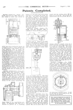
IGNITION GEAR. — Squire. — No. 27,835, dated 6th December, 1906.—A camshaft ,(a) drives, through a bevel gear, a vertical shaft (b). Keyed to this shaft, so as to slide thereon, is a sleeve (c) attached to a governor (d) which is moved up or down as the speed of the engine varies. Fixed to the sleeve is a helical gear wheel (e) engaging a similar wheel (f) on the ignition gear (g). This latter carries one, or more, face cams (h) corresponding with the number of cylinders. The lever arm (3), which makes and breaks contact with the insulated metal pin (1), is fixed on a pin (m) which turns in a sleeve (n) extending through the cylinder cover. On the upper end of the pin (m), a lever (a) turns, it is held by a spring (e) against the face cam (le). In the shorter arm of this lever there is a curved slot through which extends a bolt (q) which clamps an arm (r) to the lever. The ignition is advanced or retarded, as the speed of the engine varies, owing to the rise or fall of the gear wheel (e) under the action of the governor (d).
EXPLOSION ENGINE.—Lion.—No. 24,571, dated (under Convention) 2nd November, 1905.—Ignition" is effected by the self-ignition of carburctted gas, which is contained in a separate cylinder fed through a branch pipe from the carburetter. 38 is the working cylinder, and 39, 391 the working piston in its highest and lowest positions. The ignition cylinder (40) is cast with the cylinder (39), and its piston (41) is con
nected with the working piston (39) by means of a stirrup (42). The cylinder (40) communicates with the cylinder (38) by a passage, which is normally closed by a piston valve (44), this being pressed down on its seat by a spring (53). The piston valve (44) has a central bore (47) closed permanently at the upper end, and provided, at its lower end, with a valve (48). The piston (41), in its down stroke, lifts the valve (48) from its seat, and ignition gas mixture enters the cylinder (40) through the channel (52). On the return stroke of the piston, the valve (48) rises and the mixture of gases is compressed until it automatically ignites in the known manner. The pressure generated raises the piston valve (44), and the flame flashes through the passage (55) into the working cylinder (38).
BRAKES. — Sangster. — No. 15,706, dated 11th July, 1906.—This invention provides means for adjusting the band in a band brake, and consists of a sliding camshaft (f) controlled by a pedal which turns a lever (e) on its fulcrum (g2), and forces the band (a) into contact with the brake member (e). Abutting against the end (al) of the band (a) is an eccentric pin (d) which has a cam-like action. It will be seen that, by turning the pin (d), the band (a) can be adjusted.