


A New 30-cwt. British-built Delivery Van.
Page 18
Page 19
Page 20
If you've noticed an error in this article please click here to report it so we can fix it.
The Light Model by Commercial Cars, Ltd.
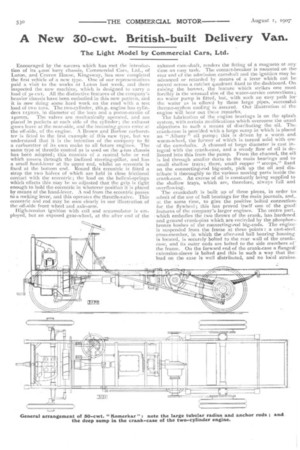
Encouraged by the success whichhas met the introduction of its 4-ton lorry chassis, Commercial Cars, lad., of Luton, and Craven House, Kingsway, has now completed the first vehicle of a new type. One of our representatives paid a visit to the works at Luton last week, and there inspected the new machine, which is designed to carry a load of 30 cwt. All the distinctive features of the company's heavier chassis have been embodied in this new pattern, and it is now doing some hard work on the road with a test load of two tons. The two-cylinder, ISh.p. engine has cylinders ristmu. in diameter of the bore and a piston-stroke of 540mm. The valves are mechanically operated, and are placed in pockets at each side of the cylinder; the exhaust gases leave at the near-side, and the incoming gases enter at the off-side, of the engine. A Brown and Barlow carburetter is fitted to the first example of this new type, but we understand that it is the intention of the company to fit a carburetter of its own make to all future engines. The same type of throttle control as is used on the 4-ton chassis has been adopted; this consists of a central tube or rod which passes through the inclined steering-pillar, and has a small hand-lever at its upper end, whilst an eccentric is fixed at the bottom end. Round this eccentric is fitted a strap the two halves of which are held in close frictional contact with the eccentric; the load on the helical-springs which effects this may be so adjusted that the grip is tight enough to hold the eccentric in whatever position it is placed by means of the hand-lever. A rod from the eccentric passes to a rocking lever, and this Operates the throttle-valve. This eccentric and rod may be seen clearly in our illustration of the•off-side front wheel and axle-arm.
High-tension ignition with coil and accumulator is employed, but an exposed gear-wheel, at the after end of the
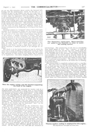
exhaust cam-shaft, renders the fitting of a magneto at anytime an easy task. The contact-breaker is mounted on thereat end of the admission camshaft and the ignition may be advanced or retarded by means of a lever which can be moved across a ratchet quadrant fixed to the dashboard. On. raising the bonnet, the feature which strikes one most forcibly is the unusual size of the water-service connections ;. no water pump is fitted, but, with such an easy path for the water as is offered by these large pipes, successful: thermo-syphon cooling is assured. Our illustration of the engine will bear out the--.:e remarks. The lubrication of the engine bearings is on the splash system, with certain mudification•s which overcome the usual. objections to such a means of distributing the oil. The: crank-case is provided with a large sump in which is placed an " Albany " oil pump; this is driven by a worm and. worm-wheel, the former of which is turned solid with one of the camshafts. A channel of large diameter is cast integral with the crank-case, and a steady flow of oil is dclivered into this from the pump. From the channel, the oill is led through smaller ducts to the main bearings and to small shallow trays; there, small copper " scoops," fixed on the connecting-rod big-ends, pick up the oil and distribute it thoroughly to the various moving parts inside the crank-case. An excess of oil is constantly being supplied to the shallow trays, which are, therefore, always full and overflowing.
The crankshaft is built up of three pieces, in order tth admit of the use of ball bearings for the main journals, and,. at the same time, to give the positive bolted connection for the flywheel; this has proved itself one of the good! features of the company's larger engines. The centre part, • which embodies the two throws of the crank, has hardened. and ground crank-pins which are encircled by the phosphorbronze bushes of the connecting-rod big-ends. The engine is Suspended from the frame at three points : a cast-steeL cross-member, in which the after-end ball bearing housimr is located, is securely bolted to the rearwall of the crankcase, and its outer ends are bolted to the side members of the frame. On the forward end of the crank-case a flanged! extension-sleeve is bolted and this in such a way that theload on the case is well distributed, and no local strains: are set up ; this extension sleeve carries the forward ballbearing and the starting-gear, which, by the way, is assembled as part of the engine and not, as is the case on so many vehicles, carried in a separate bracket which, sooner or later, loses its alignment with the engine. The nose of the extension-sleeve rests in a special bracket fixed to the front cross-member of the frame, as shown in the illustration of the leading axle ; this view also shows the mud shield which completely encloses and protects the lower part of the engine and carburetter. This principle of suspension is also carried out with the gear-box and the countershaft, and the cases of these parts are, therefore, freed of all strains occasioned by the whipping or twisting of the frame members.
The large radiator is " strapped " down to the front crossmember, as in the previous model, hut the manner of doing this has been somewhat improved to gain more strength. To each end of the steel band which passes over the top of the radiator, a double strap-bolt is riveted. The two, screwed portions of these strap-bolts are continued down below the bottom of the front cross-member and a yoke piece is then slipped over the screwed parts; the whole is nutted up tightly. The two illustrations already referred to show this. In order to assist the radiator satisfactorily to perform its work, small " fins " have been attached to the flywheel, and these, having a high linear speed, will no doubt maintain a constant current of air through the radiator.
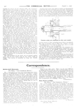
The clutch is of the leather-faced cone type in which the male cone is made in halves, in order that it may be taken down and re-leathered without disturbing any other part,. The operation of this clutch is very simple and is smooth in its application : two short, hanging levers, keyed on to the cross al-shaft, are connected by tension rods to a
hanging-bridle ; this bridle is hung from a cross-member and its lower extremities carry hardened-steel rollers which run between the flanges of the clutch sleeve. As the clutch sleeve and, consequently, the male-oone is withdrawn, the latter is brought into contact with two fixed, leather-faced, clutch stops. The thrust of the clutch spring is entirely self-contained and the clutch, as a whole, may be taken down without interfering with any other parts of the machinery. We illustrate the clutch-pedal gear as seen from the top of the chassis, and the sheet-steel " fins" on the flywheel are also seen in this view.
The gear-box is constructed en the well-known lines adopted by this company; ci-L,.r illustration (see page 527) is from the working drawing of the general arrangement. Three forward speeds and one reverse speed are provided for in its construction : all changes of gear are effected by one lever which is keyed to the upper end of a vertical shaft situated in front of the driver and near the steering-wheel. A large helical wheel is keyed to the lower end of .this shaft, and this meshes with a smaller wheel, keyed to an extension of the gear-box camshaft. The case which encloses this gear may be seen in the plan view of the chassis. On the top speed, a direct-drive is obtained and, while this is in operation, none of the gear-wheels in the box are revolving; high efficiency should therefore he obtained. All the shafts are very stiff and are mounted on
ball-bearings.. The construction of the box is remarkable
from many points of view. The " carcase " is made of aluminium or cast iron, but the two ends, which carry the main bearings, are of cast steel. The casting which closes,. in the forward end of the gear-box also forms one of thecross-members of the frame, and is securely bolted to the side-members ; the casting which shuts in the after end of the box is provided with a turned nose which is made a loosefit in a cast-steel cross-member. Thc gear-box casing, likethe crank-case, is thus relieved of all strain due to twisting of the main frame.
The counter-shaft is completely enclosed and is, a very fide job. The main drive is through bevel-gearing ; the pinion has zo teeth and the ring has 6o teeth; those are of No. 5, diametral pitch. The inner ends of the differential-shafts . are of square section, to receive the wheels of the differentialgear ; this is of the bevel-gear type. The outer ends of the• casing are supported in substantial, cast-steel brackets. bolted to the side members of the frame, and the centre of the casing is supported in another cross-member, similar to. the one which supports the after end of the gear-box. Between these two cross-members, which are stoutly braced together by means of two distance bolts, the company's patented form of coupling is mounted. It is in the form of a positive clutch, and the jaws of this are faced with stout rubber buffers; allowance is made for about 30 degrees of back-lash. It is this back-lash which allows the changespeed lever to be put into the position required for the next gear change in advance of the actual time of the change ; inomentary application of the pedal will then automatically .effect the change from one gear to another. The rear pail of the coupling has a brake-drum, cast integral with it, and two brake-blocks of the loco. pattern act on this; they are hung from the two distance bolts already referred to, and are brought into operation by the application of a pedal.
The final drive is through two " Coventry" roller-chains of if-inch pitch, with rollers five-eighths of an inch wide. The sprockets have 17 teeth, and the ratio between them and the chain-wheels is about one to three. The back-axle is kept at the correct, radial distance from the sprockets by ..means of stout, tubular radius-rods ; similar rods are employed to anchor the axle and to relieve the springs of all strains other than those due to sustaining the load. The
• ends of all these rods are bushed with gun-metal, a fact .which points to the minute attention which has been given to small details while the designs were being prepared.
In addition to the effective and powerful foot-brake, two 'brake-drums are cast solid with the rear-wheel hubs; into -these, blocks are expanded by means of double-acting levers which apply or withdraw them positively; no springs are
• employed, as is necessary when the blocks are expanded by a cam. The two wheel-brakes are compensated by reason of the twisting of the cross-shaft. The hand-lever is keyed to a tube which is free to rotate on the shaft, and, at a ;point coincident with the centre of the vehicle, a half-. coupling is also keyed; the other half of the coupling is 'keyed to the cross-shaft, and the braking force is thus -transmitted from the hand to the centre of the cross-shaft, and thence through levers keyed to its ends; side tensionrods to the lever operate the brake-blocks. In the event of a chain's coming off, or breaking, one wheel-brake still re-mains operative.
The side-members of the frame are of channel section -steel, and are four inches deep by two inches Width of 'flange. The chassis is mounted on long and flexible ,springs.
Coining now fo the axles (both of which are illustrated) it will be seen that they are built up of steel tube : the leadingaxle has cast steel ends, and the back-axle has a forged and turned steel "stub " fixed in the end of the tube. The backaxle tube is 3 inches in diameter and is three-sixteenths of an inch thick. It will be noticed that all the shafts through_ out the transmission system are mounted on ball-hearings,
and the manner of their mounting leaves little to be desired. The type of bearing used is either the " Fisher " or the " Auto-Machinery "; in both of these types there is a full race of balls and no cage is employed.
It may be of interest to know that this company has, from the commencement of its operations, adopted the "finethread " standard of the British Engineering Standards Committee. Pi'actically, this is based on a one-inch bolt having a three-quarter inch Whitworth thread; the angles remaining the same as the old standard. This new model has many points which are deserving of full consideration on the part of the prospective purchaser, and we shall expect to hear good accounts of its future work. The chassis is a workmanlike job, front start to finish, and it should wear very well in regular use.