


A Double-acting Four-stroke Engine
Page 60
If you've noticed an error in this article please click here to report it so we can fix it.
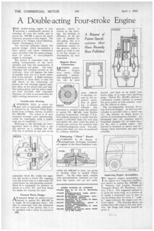
THE double-acting engine is now receiving a considerable amount of attention an over the world, and in patent No. 479,967 is shown the latest American proposal in this respect. The patentee is II. Hedges, Lloyd Building, Seattle, Washington, U.S.A.
The drawing indicates clearly the general design, which incorporates a short piston and lower combustion space provided with the usual arrangement of valves. A two-cylindered engine is envisaged.
The patent is concerned with the sealing arrangements of the lower chamber and with the construction of the crosshead and guide. The latter comprises ball bearings carried on the wrist-pin : these roll against the sides of parallel slots cut in a lower extension of the cylinder. A slight clearance is provided in these slots, so that the side thrust of the connecting rod presses the ball bearings against alternate sides, as the piston rises and falls. The sealing gland, and the piston itself. are both provided with ring-depth clearance, in order to accommodate the slight rocking movement so caused.
Variable-ratio Steering.
A STEERING BOX, in which the gear ratio is externally adjustable,. is covered by H. Thomas, Pines Edge, Sandy Lane. Cobham, Surrey, in patent
No. 480,054. The object is to give increased leverage when manoeuvring, whilst for high-speed work a higher ratio can be employed.
Referring to the drawing, the steering-Wheel shaft is fitted with a nut (2) pivoted on a rocking bar (5). This bar is pivoted at one end on an
adjustable block (6), whilst the opposite end carries a block (3) engaging with the forked end of a bell-crank (4) which forms the rod-operating member. Block 6 is adjustable for position by means of a lever (7), and thus forms the means for varying the ratio.
Unusual Piston Design.
A N unusual design for pistons is put rkforward in patent No. 480,149 by A. Gatti, 12 rue Lagbonat, Paris. The idea is concerned with the formation of the crown of the piston; this is to be provided with a series of concentric
B46
grooves, shown in section in the drawing, An increase of efficiency of 10 per cent. is claimed for this piston, due, it is stated, to secondary turbulence caused by the grooves, whilst a piston so built is said to be less subject to deformation by heat expansion.
cases, difficult to machine, except by the expensive operation of grinding. A scheme whereby this drawback is avoided forms the subject of patent No. 480,100, from Bendix Aviation Corporation, Chicago, U.S.A. This concern proposes to insert into the mould a soft-steel shaft (1) and iron pole-pieces (2), after which the alloy is poured and converts the assembly into a welded homogenous whole. The polepieces and shaft can then be machined by ordinary methods.
whilst not difficult to start, are prone to develop what is termed Diesel knock. On the other hand, engines with precombustion chambers are free from this knock, but are not easily
started, and have to be fitted with,: heater plug, or in some cases sparking, plugs. Patent No. 479,861 discloses a.' combustion system claimed to possess: the good points'of both schemess without the defects of either.
The accompanying drawing shows one of several designs. In this case the cylinder is provided with a raised cap: (1), the interior of which forms a2 species of precombustion chamber. An. interposed disc (2) contains helical = tangential passages (3), of which there are six, and a central orifice. The.-
injector is mounted as shown d.nd E, charges three horizontal jets and ono! centrally.
Improving Engine Accessibility.
improve engine accessibility is the object of a bodywork modifies; tion shown in patent No. 479,956, by E. Ottaway and London Passenger Transport Board, 55, Broadway, London, SAVA. The suggested method is to pivot the front wing, or a portion of it, about a horizontal axis so that it . can be swung clear to create a " walk-, in " space between the engine and the front wheel. The drawing shows, in broken lines, the wing in the clear position, the hinge axis being located at point 1.