


Patents Completed.
Page 22
If you've noticed an error in this article please click here to report it so we can fix it.
Complete specifications of the following patents will be sent to any address in the United Kingdom upon receipt of eightpence per copy at Sales Branch, Patent Office, Holborn, W.C.
TWO-CYCLE ENGINES.—Morrow. —No, 18,050, dated 27th August, 1908.— This invention relates to internal-combustion engines of the two-cycle type having separate ..tompressiort cylinders.
The engine comprises three cylinders arranged side by side ; the outer cylinders are working or power developing, and the middle is a compression cylinder. The middle or compression cylinder is transversely divided midway of its length, and it is provided with two pistons, one in each of the two chambers or cylinders thus constituted. These two pistons are ccnnected by a rod so that they reciprocate together. An inlet for the explosive mixture is provided in each of these compression cylinders, and each has au outlet to a working cylinder situated approximately midway of the latter's length. In line with these ports each of the working cylinders is provided with an exhaust port. The operation of this engine is as follows :— Assuming the parts to be in the position shown in the illutration ; on the downward stroke of the compression pistons a vacuum will be created in the lower compression cylinder owing to the ports therein being closed or covered by the piston in the left-hand cylinder and the piston in the compression cylinder. On the latter arriving at the limit of it;
stroke the inlet port will be uncovered and an explosive mixture will be drawn into the conivression cylinder. On the return of the compression piston the ex plosive mixture will be compressed, and the piston in the left-hand working cylinder will uncover the inlet port thereto and also the exhaust port, so that the charge in the compression cylinder will rush, into the working cylinder and assist in the expulsion of the inert gases. For this purpose the top of the piston is so shaped that it directs the incoming gases towards the top of the cylinder as indicated by the arrows. The upper compression cylinder and the right-hand working cylinder operate in a similar manner, but alternately.
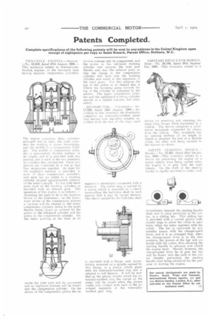
DISTRIBUTOR.-Cleveland.— No. 17,033, dated 13th August, 1908.—According to this invention the distributor comprises an internally-toothed metal ring having four segments suitably insulated from the rest of the ring ; each segment is electrically connected with a terminal. The entire ring is carried by a casing which is mounted on a sleeve surrounding the half-time shaft in such manner that it may be turned thereon. The sleeve carried by the half-time shaft is provided with a flange, and, eccentrically mounted on a spindle carried by this flange, is a pinion which gears with the internally-toothed ring and is adapted to roll thereon. It will be seen that as the pinion travels round the internally-toothed ring the circuit of the plugs will be closed when the pinion comes into contact with each of the insulated segments of the internallytoothed gear ring. SANITARY DEVICE FOR HORSES. Hunt.—No. 20,589, dated 30th September, 1908.—This invention relates to a device for receiving and retaining the dung from horses while harnessed to a vehicle. The device comprises a cylindrical receptacle suspended by chains from the vehicle. This receptacle has an opening midway of its length to which is attached the end of a flexible chute, the other end being, secured to the harness as shown.
SAFETY STARTING DEVICE. --Brooks.—No. 27,961, dated 23rd December, 1908.—This invention relates to a device for preventing the engine of a motor vehicle from being started when the engine is in gear with the road wheels. On the shaft of the starting handle is rigidly mounted a collar, and,
immediately beneath the starting handle shaft and in close proximity to the collar, is a sliding bar. This sliding bar is provided with a curved groove sufficiently large to allow the collar to pass freely when the latter registers with the collar. The bar is connected by any suitable means with the change-speed lever, and it is so arranged that, when the change-speed lever is in the free position, the groove of the bar will coincide with the collar, thus allowing the starting handle to advance and clutch the engine shaft. Should, however, the change-speed lever be in gear the bar will be drawn into the path of the collar thereby preventing the starting handle from being advanced for the purpose of starting the engine.