


Special-purpose Nut-locking Device
Page 34
If you've noticed an error in this article please click here to report it so we can fix it.
WHILST somewhat limited in its W application, a design of nut-locking device shown in patent No. 538,313 is nevertheless ingenious. The patentee is Sulzer Freres S.A., Winterthur, Switzerland. The scheme can be used only with adjacent pairs of bolts, as may be found, for example, in a heavy-duty big-end bearing. Each nut has keyed to it a superimposed washer (1); the washers are toothed on.the outer edge and form, in effect, a pair of intermeshing spur gears. In use, should vibration cause one nut to loosen, the motion is transmitted to its neighbour in a tightening. up direction. It is claimed, in fact, that the device evens out irregularities in stresses caused by unequal tightening and, after some time in Use, the bolts are found to be of uniform tightness.
A simple vernier keying scheme enables the toothed Washers to be placed in position whatever the relative angle between their nuts. Grub screws and tab washers secure them.
GAS-PETROL MIXER FOR PRODUCER-FED ENGINES
ItylANY engines using produce? gas IVI have to be started onpetrol, and patent No. 538,345 shows a junction fitting for merging the two streams of fuel. The patentees are Parkinson and Cowan (Gas Meters), Ltd.., and K. R. Green, both of Terminal House, Vic toria, London, W.1. The design is aimed at allowing the entry of gas into the induction'system with the minimum restriction, whilst alterations to the carburetter system are as small as possible. A 2-in. tube (2) from the producer is flattened into a hollow falige ( ) which is inserted between the carburetter flange (3) and the induction pipe flange (5). A straight-through bore T1) permits the uninterrupted passage of the petrol mixture, Whilst the gas, coming from pipe (2) can intermingle without disturbing theflow. Longer bolts are, of course, needed, and these are shown surrounded by inserted bushes to avoid distorting' the flange.
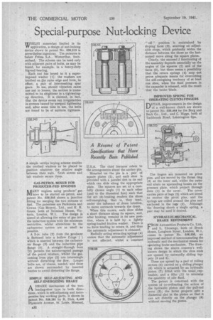
SIMPLE SELF-ADJUSTING AND SELF-ENERGIZING BRAKE
A BRAKE mechanism of the two/A leading-shoe type in both directions,.which is self-adjusting and incorporates few working parts, is shown in patent No. 538,281 by B. Dick, 6,400 Plymouth Avenue, St. Louis, Missouri, U.S.A. The chief features relate to the arrangements about the anchor pin. Mounted on the pin is a pair of square plates '(2), and each shoe is provided with a parallel slot in its end which can slide along the appropriate plate. The squares are set at a. carefully chosen angle (1) to each other (and to the diametral line) such that the act oi• braking renders the shoes .self-energizing, that is, they tend, under the influence of ,drum rotation, to move outwards towards the drum. When this occurs, each shoe slides a short distance along its square, and, after braking, remains in its new position, where it is held by a lightly spring-loaded friction washer. There is no force tending to return it, and thus the automatic adjustment is obtained. Radially acting retracting springs (4) ensure that the automatic adjustment is not affected, whilst a constant " off" position is maintained by sloping faces (3), abutting on adjustable stops, which gradually widen the distance between the shoes as the lastnamed move along the square plates. Clearly, the successf :1 functioning of the assembly depends essentially on the angles of the squares (2) and of the' faces (3), but there seems a possibility that the return springs (4) may not prove adequate means for overcoming the self-energizing tendency of at least one shoe, when the fluid pressure in the expander is released, ,with the result that the brake binds.
IMPROVED SPRING FOR OPERATING CLUTCH-FINGERS
DETAIL improvements in -the design of a well-known clutch are shown in' patent No. 538,464 by the Borg and Beck Co., Ltd., and C. Higgs, both of Tachbrook Road, Leamington Spa.
The fingers are mounted on pivot pins, and are moved by the thrust ring (3) at the inner end, whilst the outer end abuts on upstanding bosses on the pressure plate, which project through slots (1) in the cover. The cover carries pairs of lugs (2) which are bored to receive the pivot pins, and the 'springs are coiled arnund the pins and anchored in the lugs (2). Although the drawing shoWs a single spring, a pair, may be used if desired.
HYDRAULIC-MECHANICAL BRAKE REFINEMENT
CROM Automotive Products Co. Ltd, I. and L. Chouings, both of Brock House, Langham Street, London, W.1, comes in :patent No. 538,335, an improved method of interconnecting the hydraulic and the mechanical means foroperating brake mechanism. The drawing shows the above concern's wellknown design in which the shoe ends • are opened by outwardly sliding tappets (3 and 5). These are spread by a pair of rolling sectors (4) carried on a sliding plunger (6) which is actuated by an hydraulic piston (7) fitted with the usual, cupwasher, and a filler .(1) to minimize the quantity of idle fluid. The patent is concerned with the system of co-ordinating the action of the hydraulic piston and the pull-rod lever (2); the latter projects into a diametral slot in the piston so that it can act directly on the plunger (6) without moving the piston.