


The Supply Department
Page 19
Page 20
Page 21
If you've noticed an error in this article please click here to report it so we can fix it.
Selected Information which is likely to be of Interest to Makers, Owners, and their Buyers.
A Portable Engine Set for the G.P.O.
By the courtesy of the Aster Engineering Co., Ltd., of Wembley, we are enabled to supply our readers with particulars of a 5 b.h.p. Aster engine, directcoupled through an Aster patent flexible flywheel to a special D.C. generator, which has an output of 1.5 kilowatt at a voltage varying between 25 and 60. This maker tells us that the generator is specially construdted with a smooth core armature winding, so enabling the machine to work either on charging storage batteries, or direct on to a telephone switchboard. The set of which we have particulars has been constructed for the G.P.O., and forms one of a large order which have all successfully passed the most stringent tests, consisting of inquiry into fuel consumption, small cyclic variation, sensitive governing, etc. The design is neat and strong, and the whole apparatus is mounted on a steel trolley fitted with rubber-tired wheels, and which trolley is completely equipped with the necessary switch gear instruments, etc. The set is illustrated on page 54.
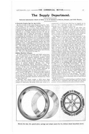
Airless Resilient Wheels.
To those owners of taxicabs and light mothrvans, who are interested in the provision of a solid-tired wheel which shall possess resilient qualities which approach or excel those of the ordinary pneumatic tire, we cannot do better than commend the airless resilient wheels which are sold by a limited company known as Airless Resilient Wheels, Ltd., whose address is Bulstrode Mews, Marylebone Lane, W. These wheels have been developed with the assistance of some of the very considerable experience which appertains to the house of Connolly, although no gentleman of that name was the actual inventor.
About a fortnight ago, we took a run upon a set of these wheels, with Mr. J. A. Connolly at the wheel of his 15 h.p. Straker-Squire car, over some rough and trying surfaces in London, and we were greatly impressed by the desirable elements of behaviour which we then observed.
Although each wheel weighs a little more than 100 lb., and a set of four costs somewhere about £75 (subject to discount), the point which any owner of a
commercial vehicle of any kind has to regard, as we have so often insisted, is that of maintenance or running cost, rather than of first cost.
These airless resilient wheels do not allow the vehicle to lurch about, on a bad surface of either macadam or sett pavement, as do pneumatic tires at times. Furthermore, from experience and records in hand, it looks as though the inclusive cost would be not more than 65 per cent, of that for pneumatics.
Our illustrations show the essential elements of the wheels. That on the left shows the outer rim, with rubber tire, and the guard plate. The inside of the rim is formed in the shape of a channel, like the lower half of the letter H. The centre part has an ordinary artillery-type wheel of wood and metal, and the sole is shaped as a steel channel like the upper half of the letter H. To this channel is fitted a series of projections fashioned like the head and neck of a duck. They are pivoted at the end of the neck and are in pairs facing one another. The crest of each head is linked to another head with a telescopic sleeve, which carries a. helical spring, and in between each pair of projections are placed a pair of twin rollers or distance pieces, which operate on the curved part. of the throat and neck. The rollers are secured to the side plates by steel bolts passing through from side to side. Each pair of projections is at an equal distance apart, and the springs are of equal length and strength. The guard plates of the floating rim overlap, and are free to slide on each side of the wheel-centre. By this arrangement, any sudden jerk or movement of the outer or floating rim operates through the twin rollers, and tends to force every one of the projections to turn on its pivot and away from its corresponding roller, thereby putting all the springs under compression equally and simultaneously. The weight of the vehicle is distributed over all the springs. The righthand illustration shows the centre portion, complete with the arrangement of telescopic sleeves and helical springs in position.
Of all the various so-called spring or resilient wheels which we have examined, this one holds out the best promise of commercial success and practical results. Cleaning the Flywheel Brake.
[1120] " F.E.D." (Poplar) writes I should like
to draw your attention to a little dodge which I.have found very satisfactory in service. It is a very simple way of keeping the foot-brakes attached to the flywheel of over-type wagons in order. These brakes collect a certain amount of grease on the bearing surfaces, and the result is that they soon lose their efficiency.
" A. simple way of cleaning them is to use a piece of waste soaked in petrol. This should be held on the wheel in a line with the brake when the engine is running; the petrol will then remove the majority of the grease on the wheel. If this treatment is given every day, the brake will be in first-class gripping order."
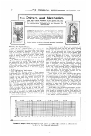
A Self-Explanatory Work-chart.
[1121] " H.J.A." (Dorset) writes :—" I am engaged in a garage where the wagons do long journeys as a rule, and we have some little difficulty in tracing the mileage covered and the tonnage carried by the wagons, as the load often varies throughout the journey. In order to enable us to see the week's work done by any of the wagons at a glance, I evolved a chart of which I send you a rough drawing. [We have had this somewhat simplified and redrawn.— ED.. It will be seen that the length shows the mileage, whilst the height shows the loads carried, The chart is marked off on the top to show the day's work of a wagon. At the bottom the various points are numbered, so that, by means of a town index at the side of the chart [Thin is not shown as it must be filled in by the driver.—Ea], the week's work of a wagon can be followed. "On the chart of which I send you a cop3r, a van left London on Monday the 12th, and went a distance of 12 miles—Harrow to be exact—with 5 cwt. of goods. It was unloaded and a new load weighing 55 cwt. was taken aboard, and then the wagon went on to Southampton, a distance of 75 miles, making a total day's journey of 87 miles. On the 13th, a journey to Bournemouth was made, and there the wagon was unloaded and went to the garage, where new chains were fitted. It was then loaded up with two tons of goods, and the next day—the 14th—it went to Handcross, and on Thursday—the 15th—it went to Balcombe. There it was unloaded, and then it proceeded empty to Hastings, a distance of 45 miles. On Friday morning, a 55-cwt. load was taken on, and the journey to Worthing--a distance of 50 miles, was made. On Saturday, the 16th, Bournemouth was reached on the return journey, and the wagon remained loaded until Monday. Each square on the chart represents five miles, and 5 cwt., this, of course, by counting the length and the height. Further, it represents 1i ton-mile so that it is a simple matter to count up the ton mileage for the week and also for each day. The chart in question shows a ton mileage for the week of 828i, whilst the distance covered was 400 miles. It would be better, perhaps, to make each division to represent four miles against the 5 cwt. load, so that each square could represent one ton-mile. " Such charts could be easily and cheaply printed, and any required additions, such as petrol consumption, details of trouble or delays, could all be put in at the side in the next column to the towns visited, in order that a complete account of the week's work of any wagon would be on record."
Securing the Radiator Cap.
The sender of the following communication has be awarded the .10s. prize this week.
[1124" 11.B." (Sandbach) writes :—" The following is a very useful little device which I have fitted to several radiator caps, in order to prevent them 'going amissing.' Very often, if a radiator cap is not carefully fixed, it works loose, and is lost on the journey ; again, drivers sometimes place a cap down when filling up the radiator in the dark, and are then unable to find it again.
"By the sketch which I enclose, your readers will see how the radiator cap or similar parts can be secured without great expense or trouble. A thin link chain about four inches long should be obtained, and this should be fitted at one end with a bar rather greater in length than the diameter of the inlet pipe to the radiator. This bar should be attached to the chain at the centre. It is an advantage to have it shaped as shown in the sketch, as the weights at the ends help to keep it in a horizontal position. The other end of the chain is soldered to the inside of the cap. Of course, you will see that the cap cannot be lost unless the bar assumes a vertical or nearly-vertical position, so allowing the chain and bar to fall out of the filling-hole. If the cap unscrews, it is still held by the bar, and the rattling will attract the driver's attention."
Wisdom for Machinists.
[1123] " W_B." (Finsbury) writes :—" I recently came across an old leaflet which I have had in my tool drawer for a good number of years. It came quite fresh to me, and much of the advice given therein is very useful in the workshop. I have extracted a few of the hints, and send them to you, trusting that they may be of interest to your readers. "Don't turn a reamer backwards. Don't file against the scale of cast iron. Don't use a monkeywrench for a hammer. Don't do government work' in the company's time. Don't try to fool your fore man, for you may get left. Don't deny spoiling a piece of work if you have done it. Don't look at the head of a closet when you are chipping. Don't think yourself above asking questions for information. Don't screw a bolt into a newly tapped hole with out o0ing it. Don't throw files, a)ne on top of another into a drawer, or on the bench. Don't make a piece of a ork too small and then bend the gauge to fit it. Don't work to a calliper that has been set by another man ; set it yourself. Don't cut the teeth in a gear blank unless you know the outside diameter is correct. Don't put a mandrel into a newly bored hole without a lubricant of some kind on it. Don't use any kind of oil but kerosene to start a shaft loose that has begun to cut. Don't try to straighten a shaft on the lathe centres, and expect that the centres will run true afterwards. Don't, think because a piece of work has been done in one way for 20 years that it is the correct way. Don't take a difficult piece of machinery apart without having each piece marked to show where it goes back."
Retrieving a Damaged Motorvan.
[1124] " J.C.B." (Dartford) writes :—" Some time ago I was ordered to bring a small one-ton van home after it had been in collision with a steam wagon. The front axle and wheels were completely wrecked, and to effect a repair on the road was out of the question. As it was blocking the thoroughfare, I had to devise some way of getting it out of the way quickly. I could not obtain a suitable trolley or a portable crane, so I rigged up a device which got me out of the difficulty.
"I 'phoned up to the garage for a four-ton lorry, which was quickly on the _scene. Pending its arrival I got a deal plank 20 ft. long, 12 in. wide and 3-3/4 in. thick. I cut oil one end of this plank to an angle of 45 degrees, and drilled a 11-in. hole through the middle of the tapered part. I then obtained two shorter planks for use as struts, and had the ends sawn so as to make a square slot when they were placed together. These two shorter pieces were then bolted . to the rear of the lorry, formmg a triangle with the lorry platform. The long plank was then placed over the top of the struts, and a 11-in bolt was put through the hole in the end and also through the platform of the four-tonner, where it was bolted up tightly from the underside. A rope-binding round the long plank and the struts then bound the planks firmly in the desired position. It was not a difficult matter to obtain light blocks and tackle and to rig it upon the projecting end of the plank, which came out about 9 ft. from the back of the heavy wagon. A sling was placed under the front part of the damaged one-tonner, and this was hooked to the blocks and the front part of the damaged vehicle lifted uo bodily. A towing rope was then placed in position between the two vehicles, in order to prevent the damaged van slipping backwards, and to prevent too much strain being put on the tackle the heavy wagon then commenced to tow the lighter van out of the way. The driver of the cripple remained on his seat, in order to apply the brake when necessary, and so to prevent t,he van from bumping into the back of the lorry. By this means, over 20 miles were covered without mishap."