


Mobile Test Unit for V.H.F. Radio
Page 61
If you've noticed an error in this article please click here to report it so we can fix it.
TO enable tests of V.H.F. transmitting equipment to be made under service conditions, the technical-commercial department of Philips Electrical, Ltd., are putting a Bedford mobile test unit into service.
The van is based upon a standard 25-cwt. chassis. The bodywork, designed and -built by London Carriers, Ltd., Bromley, is of composite construction and has a Luton head. The interior ia lined in hardboard and the floor is of adiroba. The roof is reinforced to take the weight of personnel when fixing aerials.
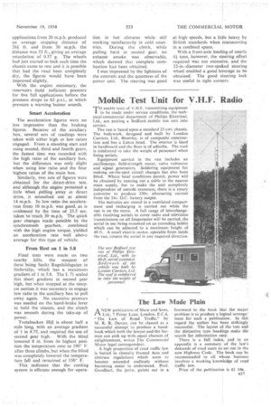
Equipment carried in the van includes an oscilloscope, field-strength meter, valve voltmeter and signal generators. Soldering equipment for making on-the-spot circuit changes has also been fitted. Where local conditions permit, power will be obtained by running out a cable to the nearest main supply, but to make the unit completely independent of outside resources, there is a rotary converter to produce 230v. alternating current from the 24v. D.C.. battery output.
The batteries arc stored in a ventilated compartment and recharging is carried out while the van is on the move. A full range of interchangeable receiving aerials to cover radio and television transmissions on all frequencies will be earned, the aerial in use being mounted on an extending ladder which can be adjusted to a maximum height of 40 ft. A small electric motor, operable from inside the van, rotates the aerial in any required direction