


An Electro-Magnetic Clutch
Page 42
If you've noticed an error in this article please click here to report it so we can fix it.
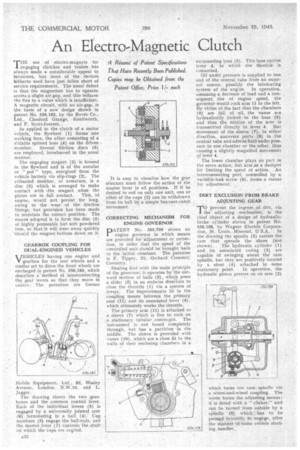
A Resume of Patent Specifications Thai Have Recently Been Published. Copies may be Obtained from the Patent Office, Price I Ieach THE use of electro-magnets for engaging clutches and brakes has always made a considerable appeal to
. • inventors, but most of the devices hitherto used have just fallen short of service requirements. The usual defect is that the magnetism has to operate across a slight air-gap, and this reduces the flux to a value which is insufficient. A magnetic circuit, with no air-gap, is the basis of a new design shown in patent No. 556,182, by the Rover Co., Ltd., Chesford Grange, • Kenilworth, and P. Scott-Iversen.
As applied to the clutch of a motor vehicle, the flywheel (I) forms one working face, the other consisting of a s:idable splined boss (4) on the driven member. Several friction discs (6) are employed, interleaved in the usual manner.
The engaging magnet (3) is housed in the flywheel and is of the annular or " pot " type, energized -from the vehicle battery via slip-rings (2). The' attracted member, or armature, is a disc (5) which is arranged to make contact with -the magnet when the plates are in full contact. This, course, would not persist for long, owing to the wear of the friction linings, but provision has been made to maintain the correct position. The means adopted is to form • the disc (5) of highly permeable but soft powdered iron, so that it will wear away quickly -should the magnet bottom down on it.
GEARBOX COUPLING FOR DUAL-ENGINED VEHICLES VEHICLES having one engine and V gearbox for the rear wheels and a similar set to drive the front wheels are envisaged in patent No. 556,183, which describes 'amethod of interconnecting the gear levers so that they move in unison: The patentees are Garner Mobile Equipment. Ltd., 82. Wesley Avenue, London, N.W.10, and L. Jagger.
The drawing shows the two gearboxes and the common control lever. Each of the individual levers (5) is engaged by a universally jointed arm • (6) terminating in a ball (4). Cup members (3) engage the ball-ends, and the master lever (1) controls the shaft on which the cups are cavied.
It is easy to visualize how the gear selectors must followthe action of the master lever in all positions. If it be desired to runon only one unit, one or other of the cups (2) can be withdrawn from its ball by a simple bayonet-catch movement.
CORRECTING MECHANISM FOR ENGINE GOVERNOR
pATENT No. 555,799 shows an engine governor in which means are provided for adjustment or correction, in order that the speed of the controlled unit should be brought back to the initial constant. The patentee is F. Tipper, 21, Orchard Crescent; Coventry.
Dealing first with the main principle of the governor; it operates by the outward motion of balls (3), which press a slider (2) in an endwise direction to close the throttle (1) via a system of levers: The improvements lie in the coupling means between the primary arm (11) and its associated lever (4), which ultimately works the throttle.
The primary arm (11) is attached to a sleeve (7) which is free to rock on a stationary tubular centre-pin. The last-named is not bored completely through, but has a partition in the middle. The sleeve isprovided with vanes (10), which are a close fit to the. walls of their enclosing chambers in a
surrounding bos (5). This boss carries lever 4, to which the throttle is
connected. .
Oil under pressure is supplied to one end of the central tube from an external source, possibly the lubricating system of the engine. In operation, assuming a decrease of load and a consequent, rise of engine speed, the governor would rock arm 11 to the left. By virtue of the fact that the chambers (9) are full of oil, the vanes ate hydraulically .locked to the boss (5) and thus the mbtion of the arm is transmitted directly •to lever 4. But movement of the sleeve (7), in either direction, uncovers ports (8) in the central tube and admits fluid under pres. sure to one chamber or the other, thus causing a slightly magnified movement of lever 4.
The lower chamber plays no part in the servo action, but acts,as a dashpot for limiting the speed of action. An interconnecting port, controlled by a variable-leak screw (6), forms a means for adjustment.
DIRT EXCLUSION FROM BRAKE ADJUSTING GEAR prevent the ingress of dirt, via the adjusting mechanism; is the chief object of a design of hydraulicbrake cylinder shown in patent No. 556,158, by Wagner Electric Corpora tion, St. Louis, Missouri, U S.A. In the drawing the spindle (5) carries the cam that spreads the shoes (not shown). The hydraulic cylinder (1) and its associated casing (3) are capable of swinging about the cam spindle, but they arc positively located by a strut (4) attached to some stationary point. In operation, the hydraulic piston presses on an arm (2) 'which turns the cam, spindle via. a Worm-and-wheel coupling. The worm forms the adjusting means; it is fitted with a " clicker;" and can be turned from outside by a spindle (9) which, has to be pressed inwardly to engage, after the manner bf'some vehicle starting handles.