


Halley' s Worm-Driven Chassis.
Page 3
Page 4
Page 5
If you've noticed an error in this article please click here to report it so we can fix it.
A Machine which has Met with Great Success Since its Introduction.
Al the last commercial vehicle exhibition, at Olympia, Halley's Industrial Motors, Limited, of Yoker, Glasgow, staged an entirely new model, and this attracted a very large share of the attention of many business men and engineers who visited the show. It impressed us, at the time, as being one of the soundest and most practicallydesigned 20-25CWL chassis in the building, and the price at which it was offered certainly commanded more than the passing glance of any who were actually " on the look-out '' for a really serviceable machine. Since the date of the show, this particular model has beconic a very popular one, and amongst the list of purchasers we note the following: Mr. Jas. Gibson, of Wishaw (repeat order); Peebles Motor Companv, Limited (repeat order); Messrs. F. Little and Company, of Newcastle; Messrs. Mackenzie and Company (India); Dalgetv and Company, Limited, of London (three); Civil Service Cooperative Society, of London; Selfridge and Company, Limit-Id, of London (six); Messrs. Bourne and Hollingsworth, of Oxford Street, W. (six); Mr. J. Wafters, of London (two); mid Mr. J. Hutchison, of Cleator Moor. Further, a large fleet of the same type of
machine is now being delivered to the Army and Navy Auxiliary Supply, Limited, of London, which society decided or this particular make of chassis after long and careful consideration of its many practical features. It is highly probable, however, that the Halley Company's successes in the R.A.C. trials of :907, and the judges' awards for the freedom from to derangement," which characterised the two Halley entries, had much to do with the decision of the abovementioned society.
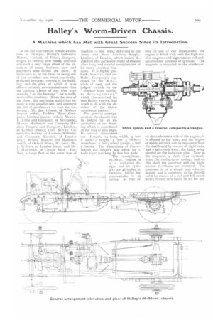
The general arrangement of the chassis may be judged by an examination of the drawing which is reproduced at the foot of this page. Its overall dimensions are : Length, 15 feet; width, 5 feet 8 inches ; height, 5 feet 5 inches; wheelbase, 9 feet ; wheel gauge, 4 feet 6 inches. The dimensions of chassi behind the driver's seat allow for a body eight feet long by five feet wide,
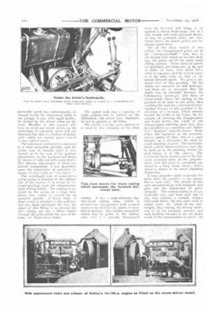
The two-cylinder, 16-18h.1L, -engine is of a well-tried de-. sign, and its cylinders are 4 inches in diameter, whilst the piston-stroke is 51 inches. As may he
seen in one of our illustrations, the engine is fitted with both the high-tension magneto and high-tension coil-andaccumulator systems of ignition. The magneto is mounted on the crankcase,
on the carburetter side of the engine ; it is clipped to the base, and the degree of spark advance can be regulated from Ike dashboard by means of rigid rods, and a bell-crank lever, the latter being pivoted on the induction pipe. Near to the magneto, a shaft rises vertically from the timing-gear casing, and on this shaft the governor and the hightension distributor are mounted. The governor is of a simple and effective design, and is connected to the throttle valve by means of a rod and bell-crank lever ; it may very easily he set for any
particular speed, but, unfortunately, although handy for adjustment when in the garage, it can, with equal facility, be altered by the driver when on the road. Readers of this journal who have in mind our recent article on the 13revention of excessive speed will understand that this is a feature of design with which we cannot agree—except in very special cases. The automatic carburetter is mounted in a most accessible position, and the piston type of throttle valve is connected, as in the case of the ignition adjustment, to the hand-control levers by means of rods and bell-crank levers. The delicate adjustment of these important components is not dependent upon the uncertainty of operation by means of wire cable or " bco;laces."
The centrifugal type of water-circulating pump is situated on the exhaust side of the engine; it is driven by enclosed gearing, from the exhaust-camshaft timing-wheel. The cooling is assisted by the action of a large beltdriven fan, which is carried on an eccentric spindle. A broad hoop of sheet metal is attached to the radiator, z-tricl this hoop surrounds the fan ; the object of this fitting is to prevent the .air's taking any but a direct course through the gills within the area of the Thoop see illustrations below.
The petrol tank has a capacity of eight gallons and is carried on the dashboard; the petrol may, therefore, be fed by gravity at all times.
The clutch is of the same pattern as is used by this company on its other
models. It has a large-diameter leather-faced sliding cone, which is pressed into engagement with a coned recess in the flywheel by means of three helical springs. Any further movement which may be given to the sliding cone, after ir is actually disengaged from the flywheel, will bring it up against a clutch brake-stop; this is a very simple and easily-adjusted device, as may be gathered front the view which shows the clutch pedals and the change-speed lever.
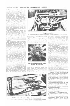
On all the oth,:r models of this maker, the change-speed gears are of the " always-in-mesh " type, but, in the chassis with which we are now dealing, the gears are of the more usual sliding pattern. Three forward speeds are provided, and these are : 4, 8, and 16 miles an hour, with direct drive when in top gear, and the reverse speed is of the same ratio as that of the lowest forward speed. We give a sectional view of this gearbox. All the shafts are mounted on ball bearings, and these are so arranged that the shafts may be threaded through the ball-bearing housings; this form of construction allows the casting of the gearbox to be done in one piece, thus avoiding the need for a horizontal joint. Another feature of this gearbox is the provision of a bracket, which extends beyond the width of the frame, for the purpose of carrying the change-speed and brake levers; the whole of the change-speed selecting gear may thus be assembled as a complete unit, before it is " dropped " into the frame. From either the repairers' or the manufacturers' points of view, this is a 1.rood feature, as it eliminates the need for much aligning of parts. The foot-brake drum, and its shoes and levers may also be built on to the gearbox, before the final fitting in to the chassis. The foot.-brake drum forms a part of the forward universal joint of the propeller shaft, and this joint is completely enclosed by a long brass sleeve, which sleeve is shown in the small adjoining illustration.
A long propeller shaft transmits the drive from the gearbox to the wormdriven back axle. The details of this axle are particularly well designed, and give one the impression of great strength. The central casing is of cast malleable iron, and from each side of this case extends a conical, tubular mild-steel sleeve, the two outer ends of which carry the whole of the axle weight, thus leaving the driving shafts free of all but torsional stresses and such bending stresses as are the direct result of the transmission of power. All the shafts are in on ball-journal
bearings, with ample provision, by means of double-thrust bearings, for the • taking up of all end loads, The worm -1-utft is made of" ebas " steel, care lly hardened and ground. The pitch of the worm teeth is one inch, and it has seven leads; the circumferential .1 lead of the phosphor-bronze worm wheel for each revolution of the worm is, therefore, seven inches. The worm wheel has 42 teeth, and it is bolted to a inalieable-iron casing which contains the bevel-type differential gear, and the main bevel wheels of this gear are keyed on to the inner ends of the axle shafts. The last-named shafts are turned from hammered bars of five-percent, nickel steel.
The rear road wheels, of course, ride .on the outer sleeves of the axle, and rotary motion is transmitted to them- front the differential shafts—through the medium of claw-clutch pieces which are secured on to the outer ends of the shafts; the claws engage with corresponding projections on the wheel hubs, as shown in the small illustration on this page.
The foot-operated brake, as already stated, acts upon a drum ‘vhich forms an integral part of the forward uni versal joint of he propeller shaft. The shoes for this brake are pivoted on a bracket that projects from the bottom of the gearbox casting. The side-lever brakes, however, are of the internal expanding type, and they act within drums that :ire directly secured to the rear road wheels. The brake shoes and levers are clearly shown in the elevation (general arrangement draw ing) which we reproduce on page zoo; each shoe is of crescent form, and is pivoted to a curved lever which, in tarn, is hinged to a bracket that pro jects from the axle casing. As the curved levers are forced apart by the action of the operating cams, the brake shoes may take up a position in which ihey present a maxhnum amount of surface in contact with the interiors of the drums. The amount of machining done on the shoes themselves is very slight, and I hey are, therefore, cheaply produced, and easily renewable. The pull of the hand lever is balanced between the two wheel brakes through
the medium of a steel cable and a short equalisingshaft.
The axle is anchored to the main members of the frame, by means of a radius rod at side of the chassis, and the whole casing is prevented from ro toting by a triangular torque rod, which is held up to the middle transverse frame member by means of a hanging link, As will be seen from our illustrations, the frame is of pressed steel, and it is mounted over the axles by means of semi-elliptic springs. The front springs are provided with the usual form of suspension links, whilst the ends of the rear ones slide in slippers which bear on brackets that are attached to the main frame. All the spring pins, links, and slippers are provided with grease caps. The photographs from which this article is illustrated were specially taken for the purpose, by permission of Mr. D. McN. Sharp, who reptesents the company in London. His office is at 25, Victoria Street, Westminster, S.W. Mr. Sharp went round practically the whole course of the R.A.C. trials itinerary, in September and October of last year, and arranged, both then and subsequently, a considerable number of Halley agencies. He will be pleased to hear from responsible parties in any centres for which the company has not yet made its selling arrangements. There is no question that this make of vehicle presents considerable attraction, and good selling points, for the attention of all who are desirous to add the selling of utility vehicles to their existing motor or other businesses.
D1TORIAL communications must be sal' dressed to The I aitor," and should reach the London Office not later than let post on Monday, if intended for the following Thursday's issue. The Editor does not hold himself responsible for the safe keeping or return of anything submitted For his consideration ; but if stamps are enclosed. MSS.. drawings Or photographs which are not considered suitable will be returned, All articles, drawings, photographs, and other contributions paid for and published in this journal are the copyright of the poprietors of 'Tin Commercial Motor,from whom alone authority to republish can be obtained.
All letters regarding advertisements, subscriptions, and other business matters must be addressed to "The Manager."
The circulation of "The Commercial Motor ' is certified monthly by a firm of Chartered 4.-vountants.
Far further information regarding Subscriptions. ivertisements, Deposit System. etc., see " Notices," Column 1 of Sundry Advertisements.