


Patents Completed,
Page 20
If you've noticed an error in this article please click here to report it so we can fix it.
GAS TURBINE.— Compagnon.— No. 8,321, dated 14th April, 1908.—This invention relates to a turbine actuated by the products of combustion of carburetted air. Compressed air is supplied from a reservoir (1) through the pipe -(2) to a three-way cock (3) one way of which is connected to the petrol supply cock (4). The air and petrol is forced from the cock (3) through a carburetter (5) to the combustion chamber (6) where the mixture is ignited by electricity. The products of combustion flow into the buckets (7) that are provided on the periphery of a turbine wheel which is arranged to rotate within the casing (Si. The casing (8) has stationary pockets (9; so that the gases passing out of the buckets (7) expand in the pockets, and, by re-action, increase the force acting on the turbine wheel. The carburetter (5) comprises equal numbers of superposed metal discs (10), asbestos discs (12) and metal gauze discs (13). The metal and asbestos discs are provided with a central hole which forms a vertical conduit (14) through which the gauze discs extend and act as baffles to effect the mixture of the air and petrol. In order to keep the combustion chamber cool, compressed air is allowed to flow through the conduit (15) into a jacket (16) surrounding the combustion chamber, where it expands and then flows through a tube (17) to the buckets on the turbine wheel.
PETROL-ELECTRIC T leANSM. ISSIGN SYSTEM.--Midgley.—No. 28,143, dated 20th December, 1907.--According to this invention the engine drives a dynamo having two armatures, one of which only has a small number of coils to generate sufficient electricity to energise the field magnets. The engine (a) is directly coupled to a dynamo having two armatures (c, cl). The armature (t) has only a small number of coils (e) which are adapted to energise the field magnets (f, f), while the armature (d) is wound with coils (hi adapted to take the full power of the engine (ai. The usual shunt
circuit (f) is provided from the armature to energise the field magnets. The field magnets (1, f) are adapted to move
in an axial direction on guides (di) over the armature (c, di so that the voltage of the current generated can be increased as the field magnets are moved over the armature (di, and rice verse. The movement of the field magnets (f, f) is effected by suitable hand-operated gear. The cerrent collected by the brushes (it is conveyed to electro-motors (k) which drive the road wheels of the vehicle.
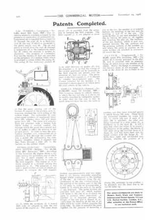
VEHICLE WH EELS .—Ferranti, —N o. 21,726/1907, dated 1st October, 1907.— This invention relates to vehicle wheels, in which the tire and Tim as a whole can be readily detached by collapsible spokes. In order that the tire may in turn be easily removed from the rim, the latter is
divided circumferentially into two members (a, al), having outwardly extending flanges which correspond to the beading of the tire. At intervals along the circumference of the rim corresponding to the sparing of the spokes, part of the rim is cut away in order to accommodate a holder (b) in which the ends of the spoke (c) are disposed. The spoke holders are erovided with pins (d), which register with holes in the rim so as to retain the parts in position when assembled. A member (e) is disposed between the flanges of the rim and is shaped to accommodate the beading of the tire at its sides while its tipper surface supports the inner tube. In order to assemble the parts together for the purpose of mounting a tire on the rim, the member (e) is inserted between the headings of the tire and the portions ia and al) of the rim. The spoke holders (b) are next attached to the rim by forcing the parts (a, al) together and inserting the pins (d), the resilience of the tire beading, which is now compressed between the rim portions and the gripping surfaces of the member (e), will retain the parts in position as tlx spoke holders are attached in succession all round the rim.
CLUTC H. — Wrigglesworth. — No 28,460, dated 27th December, 1907.—Tht pulley (2) is loosely mounted on the shaft (3), and is provided with an extensior flange (4) which forms one member of the clutch. Within the flange or extension (4 two friction shoes (5) are arranged. Tie ends of the shoes (5) are inclined to oat another, and they have dove-tail groove in which blocks (10) slide. These block are connected together by screw bolt ill), to which one end of each of th links (16) is attached ; the other end: being connected to a slide collar (1), at feathered on to the shaft (3). It will t seen that when the collar (1) is moved i the direction of the pulley, the blocks al will slide along the inclined faces of tt shoes (5), and will force them into fri: tional contact with the flange (4). Ti bolts have right and left-handed acre threads, whereby the position of a
blocks (10), relatively to one another, c. be adjusted, and the slack due to we can be taken up.
Our patent abridgments are made by Messrs. Souk, Wade and Tennant. International Patent Agents, Ill and 112. Hatton Garde., Londoa.