


Patents Completed.
Page 28
If you've noticed an error in this article please click here to report it so we can fix it.
Complete specifications of the following patents will be sent to any address in the United Kingdom by the Sales Branch, Patent Office, Holborn, W.C., upon receipt of eightpence per copy.
A Crossley Vaporizer.
K. I. Crossley and W. Le P. Webb, No. 15,814, dated 6th July, 1912.—In internal-combustion engines working on a four-stroke cycle, and fitted with a vaporizing chamber which communicates with the working cylinder by a contracted neck, the air admission valve, according to this invention, is situated in, and completely surrounded by, a water jacketed portion of the vaporizer. Preferably it is situated exactly opposite to the contracted neck, so that the air flows straight across the vaporizing chamber, and the oil is injected at right-angles to the path of the air. The unjacketed portion of the vaporizer is opposite tho fuel nozzle, and the exhaust valve is arranged in the end of the working cylinder. The advantage of this construction is, that the air is not unduly heated before entering the vaporizer.
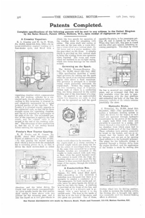
Fowler's New Tractor Gearing.
R. IL Fowler and H. Cooper, No. 21,632, dated 23rd September, 1912. Patent of Addition to No. 13,784, of 1911. —In this gearing the second motionshaft which is driven from the crankshaft has a reversing pinion an it, £0 that it drives the third motion-shaft in either
direction, and the latter drives the fourth and road-wheels correspondingly. An extra spindle beside the first motionshaft carries a loose sleeve with two pinions for the reversing gear, and it also has keyed on it two gear-wheels to
obtain the two speeds for operation of the winding drum for ploughing with cables. The extra shaft also carries at one end, on the near side, a worm driving a worm-wheel on a vertical shaft. On the lower end is a pinion meshing with the gear-wheel on the drum. A suitable clutch is provided on this vertical shaft to bring the winding drum into operation when required. The worm and wormwheel are enclosed in an oil-tight casing, which also forms bearings for the clutch sockets.
Governing on the Spark.
The British Thomson-Houston Co., Ltd.; No. 16,442, dated 13th July, 1912. —This specification describes a centrifugal governor for cutting out the spark when the speed of an internal-combustion engine rises above a fixed maximum. The governor is arranged in a circular casing which preferably surrounds the engine-shaft. Within the casing there are two insulating rings of TT-section, within each of which is a conducting ring, one being connected to the centre binding post of the distributor of a magneto. As applied to an eight-cylinder engine two magnetos are used, so that each can be operated on half the speed
which would otherwise be necessary. On the engine-shaft is a clamp carrying a pivoted weight which can swing out under the action of centrifugal force, being at the same time controlled by a spring. Flexible brushes are connected to the weight to make contact with each ring, so that, when the speed becomes excessive, contact is made with the rings, tha sparking plugs are cut out, since the distributor is then connected directly to the frame of the engine, through the contacts and shaft.
A Conductorless Bus.
L. C. Huppet. A. F. Paul. and A. J. Tanner, No. 9476, dated 22nd April, 1912.—According to this invention a motorbus is so designed that there is no necessity to employ a conductor on it. The passengers, for both inside and outside, enter by gates beside the driver so .that he can take the fares. A platform is provided at the front of the bus, and on one aide of it a driver's seat is arranged, with a stair behind it to the outside seats. The door to the inside of the bus is at the foot of the stairs, and two gates are provided. One of these,
opposite the stairs, is for passengers getting off, and is opened by the driver. When they have left, this gate is closed and the other gate opened, admitting incoming passengers. The steps by which
the bus is mounted are coupled to the gates, and so arranged that they are only available when the gate is open. By dispensing with the rear platform and extending the body of the bus, the passenger capacity of the vehicle remains practically the same.
Hydraulic Brake.
C. Primavesi, No. 28,904, dated 16th December, 1912.—This specification describes a. hydraulic braking system in which the levers for the brakes on each wheel are operated through hydraulic transmission by the power of the engine. A supply tank filled with water and glycerine is connected to a pump, and thence through a stop cock to a distributor chamber, from which pipes lead to cylinders beside each of the four wheels. These cylinders have pistons connected by levers to the brakes, and are so arranged that the brakes are held off by springs, and are put on by opening these cylinders to the hydraulic pressure. The pump for the hydraulic system is operated through a friction drive from the engine flywheel, and the application of the brakes is made by moving this friction wheel into its driving position. In order to increase the braking action, the friction disc is brought into operation repeatedly until the desired braking effect is obtained.