


A CURIOUS TRANSMISSION.
Page 32
If you've noticed an error in this article please click here to report it so we can fix it.
A Resume of Recently Published Patents.
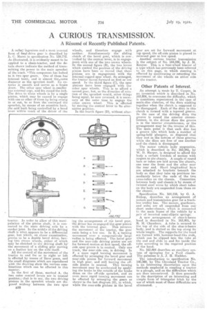
A rather.ingenious and a most unusual form of final-drive gear is described by L. C. Muret in specification No. 139,772. As illustrated, it is evidently meant to be applied to a chain-tractor, and the details shown indicate the method of transmitting the power to the main sprocket of the track. a This component. has bolted to it two spur gears. One of them has internal teeth, and is almost the4same diameter as the sprocket itself. Its exterior is smooth and serves as a•brake drum. The other spur wheel is.smaller has external cogs, and fits round the hub. The drive to these wheels is by a single pinion, which may be caused to engage with one or other of them by being swung in or out, to or from the centreaof the sprocket., by means of an eccentric bush, the said bush being controlled by a hand lever within reach of the driver of the
tractor. In order to allow of this manipulation of the pinion shaft, it is connected to the main driving axle by a eardan joint In the midd:e of the driving shalt is what appears to be a differential gear, but. which, on closer examination, proves. to be a double bevel drive, hay, Mg • two crown wheels, either of which May be clutched to the driving shaft by the .movement• of a sliding gear moving on a feather key on the axle itself.
All the control of the movement of the tractor to -and fro or to right or left is effected by Means of these gears, and the small diagrams which are reproduced with the drawing show the various combinations Which can be effected in this manner.
In the first of these, marked A, the two outer control levers are in neutral position; that is to say, the two driving pinions in the sprocket wheels are disposed midway between the two spur 1336
wheels, and therefore engage with neither. Simultaneously the sliding clutch of the bevel gear, which is con. trolled by the central lever, is in engagement, with one of the two crown wheels. In the second figure (B), the two levers which control the position of the driving pinion have been so moved that those pinions are in engagement with the Internal cogged spur wheel. So arranged, the tractor moves forward on first or low speed. In the third figure (C), the spur pinions have been engaged with the other spur wheels. This is to afford a second gear, but, as the direction of rotation of the sprocket would, other things being equal, be now reversed, it is necessary at the same time to engage the other crown wheel. This is effected by moving the central lever to its alternative position.
In the fourth figure (D), without alter ing the arrangement of the bevel gear, the driver has re-engaged the spur pinion
with the internal gear. This reverses the movement of the tractor, the gear ratio -being a low one. In E, a turning movement over a comparatively large radius is being effected. The bevel gear and the near-side driving pinion are set for forward motion at first speed; the offside spur pinion is in neutral. Only one track, the near-side one, is driving. In F, a more rapid turning movement is effected by arranging the bevel gear and near-side pinion for forward movement in high gear, and still leaving the off
side pinion in neutral. This turning movement may be accelerated by applying the brake to the outside of the brake drum on the off-side sprocket, and an even more rapid turning movement can be effected by arranging the gears as shown' in the last diagram (G), in which, while the near-side pinions in the bevel gear are set for forward movement at top speed, the off-side pinion is placed in reversed gear at low speed.
A-nother curious tractor transmission is the subject of No. 164,230, by J. M. Kroyer. This is a four-wheel tractor of a type which has previously been referred to on this page, in which steering is effected by accelerating or retarding the movement of . the wheels on either side of the tractor.
Other Patents of Interest.
An attempt is made by T. Cooper, in an invention which is described in No. 163,804, to overcome the difficulty, which is sonietimes experienced in the case of multi-disc clutches, of the discs sticking together when the ,clutch is supposed to be disengaged. Each of the discs in this clutch is formed with a tapered groove. In the case of the driving discs the groove is round the exterior circumference, in the driven discs the groove is in the interior circumference, or the arrangement may be the reverse of this. The main point is that each disc has a groove into which beds a number of spring-held plungers, So disposed . that they rest in the bottom of these grooves when the discs are free of one another and the clutch is disengaged.
The motor vehicle body suspension, which is described in No. 163,941, by W. D. Harper, is designed to afford the body. a certain freedom of motion with respect to the chassis. A couple of round bars or tubes are laid across the chassis, one near the front and the other near the rear end. Short longitudinal bars are attached to brackets beneath the body so that. they take up positions immediately below the ends of the twq cross-tubes on the chassis. Connection between body and chassis is by means of twisted steelv wires by which short tubes on the body are suspended from those on the chassis.
Specification No.164,118, by G. A.
Bishop, 'describes No.arrangement of motors and transmission gear for a trackless trolley bus. The motors, gearboxes, and axles are all suspended from one' short under-chassis, which is connected to the main frame of the vehicle by a pair of inverted semi-elliptic springs.
A new arrangement of char-a-bancs hood is described in No. 163,905, by R. M. Chambers. A.tube is secured to the top of the side of the char-a-banes body, and is slotted at the top along its whole length. The supports for the hood are formed with hammer-head-like ends, which can be slipped into the tube at the end and slide to and fro inside the tube according to the required position of the hood.
No. 163,894 describes an auxiliary system of springing for a Fora chassis. The patentee Is A. J. H. Haddan.
The introduction to specification No. 140,389, by The Cleveland Tractor Co., is an interesting dissertation upon the methods employed in coupling a tractor to a plough, and on the difficulties which are then encountered. It then proceeds to the description of an interesting and simple form of triangular hitch by the use of which most of 'these difficulties are eliminated.