


Castellated Shafts for Motorcars and Some Test Results.*
Page 15
Page 16
Page 17
Page 18
If you've noticed an error in this article please click here to report it so we can fix it.
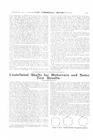
Square shafting was introduced when Levassor made the first gearbox with its system of clash gearing, and it is still used, with the edges rounded off, to a suitable extent, in a good many cars. Other makers have used long keys pinned in key-ways cut in the shaft, or alternatively projecting keve pinned directly on to the shaft.
The best and the latest practice, however, is to use casteI
d shafts similar to those tested and here reported upon by the author, or alternatively shafts of the form shown in Fig. 3. In either case the grooves and key-ways it, thg sleeveor boss are :rut out 80 as to leave solid projections or keys corresponding to and fitting in grooves or key-ways in the shaft. In every case where gear wheels are moved into engagement there muse be no constraint with respect to axial movement :dung the shaft, while at the same time the fit. should be good enough to prevent rotational play of the wheel on the shaft. If tile first condition is to be fulfilled, it follows flirt the shaft elealld be made stiff enough, i.e., its diameter shoeld be large enough so that when the maximum torque is broil:silt to bear riper the shaft it should not cause spring or t whet sufficient to resnit in binding between the shaft projectiens arid the sleeve or boss of the wheel. It i$ well known i ii general engineering practice that if the spring is Co he taken into acconnt, the diameter found by calculation is larger than it would he if the strength or resistance of the shirt.' alone were considered, and the motorcar manufacturer has also foiled that gearbox shafting should be designed from enneiderations ni stiffness rather than from those of strength.
Motercar manufacturers have funnd front experience that in Form, cases shafts have taken a slight set, rendering it difficult to slide the gear sleeves along without considerable friction,
and so it is becoming the practice to use comparatively heavy shafts as compared with the power transmitted. The author's experiments have shown that the exact torsional limits ot elasticity for shafting are much lower than the figures representing yield points, which are published in works dealing with the strength of material, and thus to some extent account. for this heavier shafting, which experience has shown to be necessary.
In addition to the torsion, the bending action in the case of gearbox shafting due to the load on the teeth of the wheels is mealier factor adding to the diflieulty of arriving at suitable dimensions of shafting for a ear of given power. Though in some cases the effect of the gear sleeves is to stiffen up tho shafts to the extent of spreading the bending load, in any case the maximum bending moment as well as the maximum twisting moment should nevertheless be considered ir, fixingthe dimensions of the shaft-.
With respect to the kind of material used for gearbox and clutch shafting, soft mild steel seems hitherto to have been the favourite, and steel containing about 0.15 of one per cent_ carbon is very useful for case-hardening, which at the present time seems to be It practice adopted in order to prevent thedevelopment of slackness between the shaft and the boss_ The various forms of the alloy steels are, however, being used in addition, notably a steel containing about three per cent__ of nickel. The elastic limits of such alloy steels aree considerably above those of mild steel, and in the case where the material has been oil-hardened or treated, the limit is much above that for the same kind of material when tested in the ordinary untreated condition.
The desirability of making torsion tests on shafting, both of the plain and castellated forms, before building it up into
Figs. 4 and 5. Including angle u£ key-ways.
the motorcar does not yet seem to be fully realized—it is thought by some firms quite sufficient to make occasional tensile tests. First-class firms may, and perhaps do, in the case of crankshafts have a tension test made on a piece of steel cot from each shaft, and as to the wisdom of this course, failing a torsion test, there can be no doubt whatever. The author has tested a large number of specimens cut from motorcar crankshafts, and has been considerably surprised at the immense difference in the behaviour of different specimens prepared from the same charge—the results showing both very ductile and very brittle conditions of material. Although comparative results of value are obtained from tension tests of material to be used as shafting, vet undoubtedly results of more practical value would be obtained front the testing of the material for that kind of stressing action to which it is
to be subjected in regular work. There is, further, the strong probability that tension and torsion tests will be found in some respects to be complementary.
Speeification for Torsion, Teel .—Taking for granted, then, that the torsion test is more valuable than the tension test in such cases, the ipiestion arises as to what results should be given in a report or required by a specification. The author ugpsts the following as covering all results of practical importance :
(1) The torque at the elastic limit and, for cylindrical specimens, the corresponding shear stress at this limit.
(2) The ratio of the torque to the angle of twist for the elastic period together with the angle of torsion at the elastic limit. (3) The elastic resilience or work per unit length and per unit volume, at the elastic limit of the specimen. (4) The maximum torque. (5) The ratio of the torque at the elastic limit to the maximum torque. (6) The total work per unit length and per unit volume required to twist the specimen to destruction. (7) The ratio of the total plastic. work to the elast's work. (8) The angle of torsion per unit length and the angle of the helical lines of twist.
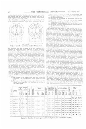
(9) The appearance of the fracture. The author gives the results of some torsion teats on two qualities of material, mild and nickel steel; with the former, the tests were made on solid cylindrical and castellated specimens, and with the latter on castellated specimens tested in the normal condition, and after oil-hardening. The complete numerical results for the mild steel specimens are given in Table I., and for the nickel steel specimens, in 'table IL The principal objects of the experiments on the mild steel specimens were to determine (1) the effects produced on the elasticity and strength by castellating ur grooving the shafts; (2) the equivalent diameter of a solid cylindrical shaft which would have the same angle of torsion at the ellstic limit as the castellated shaft, or in other words, the diameter of a shaft which would have the same value of the ratio elastic torque to twist; (3) if possible, the diameter of a solid cylindrical shaft which would have the same moment of resistance as the castellated one.
For this series of experiments four pails of specimens were prepared, one specimen in each pair having six key-ways, while the other specimen was a plain cylinder with a diameter the same as that at the bottom of the key-ways for the castellated shaft. The largest castellated shah was 2 in. outside diameter with the corresponding plain specimen 2 in. dia meter, and the smallest castellated shaft was 1i in. outside diameter with the plain specimen 1 in. diameter'. The angular extent of the key-ways is shown in Figs. 4 and 5.
As will be seen by reference to the tables, the dimensions given both for the mild steel and the nickel steel specimens fully cover those used for shafting embodied in the construc• tion of a chassis, and this being so it is hoped that the test results will be of considerable practical value.
Mild Steel Test Results .—Comparing the figures for ths several pairs of the elastic limits given in column 7, Table I., it will be seen that in each case the limit for the plain specimen, whose diameter is the same as that at the bottom of the key-way of the castellated shaft, 18 somewhat less than that for the castellated specimen, showing, as might be expected, that a little additional strength is afforded to the larger shaft by the projections. This result is borne out, too, by a comparison of the torques at fracture given in column 14, where in each case the torque at fracture for the castellated shaft is greater than that for the corresponding plain shaft. When, however, we come to compare the work required to fracture the material we find that, with one exception, more work is required to fracture the plain specimen than the corresponding castellated specimen, from which it
may be inferred that in the ultimate part of t he test the castellations become a source of weakness.
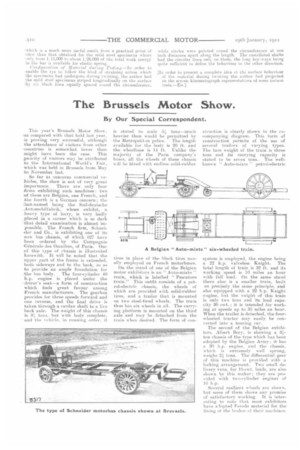
In order to find the equivalent elastic shaft or the diameter of a shaft which will give the same spring or angle of torsion as the castellated shaft for values of torque up to the elastic limit, we must take the usual formula for the rigidity modulus for a plain cylindrical shaft, and evaluate for the diameter—substituting in the formula the value of the ratio torque/twist found experimentally for the castellated shaft, and this is tabulated in column 8.
This is shown symbolically as follows:—
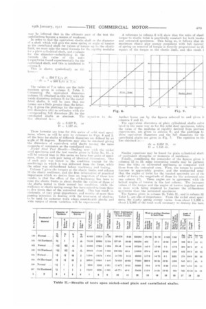
G = 584 T L/a d4. , •• • de -= 4 1/584 L/G x The values of T/a taken are the italic numbers given in column 8, Table 1. Comparing the equivalent diameters (column 11) obtained in this way with the inside diameters (column 4) for the castelfated shafts, it will be seen that the former are a little greater than the latter. Fig. 5 gives the plottings for the equivalent diameters (de) as ordinates with the corresponding full diameters (D) for the rasteliated shafts as absciss. The equation to the line obtained is:— I • de = 0.857 I), or D = 1.167 de.
These fermnlai are true for this series of mild steel specimens, where, as will be seen by reference to Figs. 4 and 5. all the keys for shafts of different diameters an. defined by an angle of 28 degrees. Equations may also be obtained giving the diameters of equivalent solid shafts boring the same moments of resistance as the castellated ones.
-ViekAl Steel Te4 Result.?.—Dealing next with the nickel steel specimens and the test. results given in Table No. II., it will he noticed that in this series we have flour pails of specimens, those in each pair being of identical dimensions. One of each pair was tested in the condition (except for the machining) in which it was delivered from the forge, while the other was oil-hardened before machining and testing. Column 7 gives the torques at the elastic limits, end column 10 the elastic resilience., and the first information of practical importance which we derive from an inspection of these test. results is that the effect of the oil-hardening has been to raise the elastic limits to about double the values of those of the shafts tested in their normal bar condition, while the resilience or elastic spring energy has been raised to from three to five times that of the untreated shaft. This last result is. obviously:, of very great importance, and worthy if more than passing attention in dealing with the treatment of shafting to be used for motorcar work where considerable shocks and wide ranges of stress (.ariation will be experieneed.
A reference to column 8 will show that the ratio of elasti torque to elastic twist is practically constant for both treat& and untreated specimens. This being so, it follows that th maximum elastic play energy consistent with full recover, of spring out removal of torque is directly proportional to th square of the torque at the elastic limit, and this result i Similar equations may be found for plain cylindrical shaft. of equivalent strengths or moments of resistance.
Finally, considering the remainder of the figures given ii columns 12 to 19, some interesting results may be gathere( from the te•sts on oil-treated specimens as compared wit] those from the untreated ones. First, the torque. to product fracture is appreciably greater, and the unexpected resul that the angles of twist for the treated specimen are of tin order of twice the magnitude of those for the untreated one ism column 17). These angles are in agreement with tie helical angles of torsion in the last column. The increase( values of the torque and the angles of torsion together resul in Imre work being required to fracture the oil-hardene( sp-ximens than the untreated specimens.
The. figures given in column 16, Table IL, and in column 18. Table I.. are also of importance. From the nickel steel speci mens the elastic spring energy varies front about 1/1,000 t( about 1/2,000 of the total work necessary to destroy the bars,
-which is a much more useful result from a practical point of 'view than that obtained for the mild steel specimens where ..mly from 1.11,000 to about 1/26,0130 of the total work energy in the bar is available for elastic spring. Configuration of Material during rezting.—In order to .enable the eye to follow the kind of straining action which the specimens had undergone during twisting, the author had the mild steel specimens striped longitudinally on the surface ly six black lines equally spaced round the circumference, while circles were painted round the circumference at one inch distances apart along the length. The castellated shafts had the circular lines only on them, the long key-ways being quite sufficient to define the behaviour in the other direction.
[Iii order to present a complete idea oi the surface behaviour of the material during twisting the author had projected on the screen kinematograph representations of some torison tests.—En.]