


Simplicity the Keynote of Two-stroke Balancing System
Page 22
Page 25
If you've noticed an error in this article please click here to report it so we can fix it.
Solution to Problem of Obtaining Good Balance with Multi-cylindered Inline Two-stroke Engine, without Complexity of 'Mechanism, Advance' d by .
Sourer Concern •
LARGE and sn4all internal-combOtion engines operate in considerable numbers on the two-stroke cycle, but medium-size units, such as those o1. commercial vehicles and cars, are nearly all four-strokes. In marine engineering, and in industry, the relatively low-speed two-stroke Oil engine is highly successful, whilst the majority of 'lightweight motorcycles, some in the bigger classes, and many appliances, mobile and Stationary, from. mowing-machines upwards, rely uPon the. two-stroke engine and constitute incontrovertible evidence that it, is a satisfactory and economical proposition.
Why. then, .has the two-stroke so few supporters in road-transport fields? Is there another British two-stroke commercial vehicle besides the Trojan, which; indeed, has manfully kept the two-stroke flag flying for over two decades? There are British road rollers and tractors with low-speed two-stroke engines, and there is the recently introduced General Motors two-stroke vehicle engine in America, of which we expect to hear more. There, are—or were—several Continentirvehicles of this type. But the fact remains that for road vehicles of all classes in this country' the four-stroke reigns supreme.
Specific Problems of Straight Two-stroke
We suggest that one iMportant reason is that the high-speed twostroke engine, of the multi-cylinclered type and with its cylinders in line, presents balance problems which a:re more difficult of solution than those of the four-stroke. It is the " tilting forces " that cause the trouble. Whilst the crankshaft of a four-stroke fourors., ,six-cylindered engine with regular firing intervals is symmetrical, that of a two-stroke is not.
• One might say that the very feative which militates against the type lies within the cause of its attractiveness, because, in the case of the " four," the four impulses per revolution, which, on one hand, necessitate ttie • unsymmett cal shaft, render it, on the other, 'the equivalent of a four-stroke " eight," in respect of' firing frequency. We would like to add, and of power output
for equal bore and stroke, butrefra:n from doing so, knowing how 'controversial this question is.
In low-speed engines these tilting
forces are not serious, but in highspeed units they become definitely
objectional, because their magnitude increases as the square of the crankShaft revolutions per minute.
One method that has been, employed to remove this obstacle 1vas the use of _ two pistons per cylinder. Clearly this scheme brought with it a marked • increase of complexity and an engine of dimensions somewhat awkward from the point of view of accommodating it in a mfitor chassis.
Another .system, made . use of six cylinders, arranged in two hanks of three, set at 60 degrees to one another. In this instance, the tilting forces of the first order were balanced by two masses revolving at engine speed, at the front and rear respectively, and driven by gears, whilst those of the second order were countered by similar masses, similarly positioned and driven, but running at twice crankshaft speed.
• weight, was yet a third method. The plan, in this case, was to counterbalance completely and individually all rotating forces, leaving only the reciprocating forces which were confined to a vertical, central, longitudinal plane. The tilting moment resulting from these was balanced by a pair of eccentric masses 'rotating in opposite directions at the .front and another at the rehr. In this scheme the use of one additional shaft (assuming that two of the masses were driven by an existing camshaft) was unavoidable, together, of course, with the associatedgearing, etc. •
In view of the foregoing it is 'of no mean interest that the problem can be satisfactorily solved without the. employrnerkt of any extra mechanism, excepting balance weights, provided that the. engine is of the type incorporating one shaft besides the crank shaft, • as would be the case in a unit having cam-operated valves, which is common practice: The scheme has been patented by S.. A. Adolphe Saurer, of Arbon.. (Ref., B.P. -Specification 549,750,) To appreciate the ingenuity of the system, it is first desirable tO examine how the balance problem is tackled for any one cylinder. The Well-known. practice .of employing counterweights preponderating over the rotating masses by half the mass of the reciprocating parts is followed. , Thus, as the crankpin moves from 12 o'cloCk to 3 o'clock the unbalanced reciprocating forces fall from maximum in an upward' direction to zeros whilst the.. radial rotating unbalanced forces rise from zero to maximum in a direction from the axis through 9 o'clock. As • the two forces have maximum values of equal magnitude, it is clear that . their resultant force will be constant moreover itsdirection will move angularly from-12 o'clock to 9 o'clock,
• in an anti-clockwise direction, as the Crankpin travels, clockwise, from 12 to 3 o'clock. •
A Constant Rotating Unbalanced Force
This state of affairs is reproduced for the next quarter revolution, and so on, and accordingly it is clear that the out of balance force for each cylfflider constitutes a force of constant magnitude rotating at the same speed as the crankshaft, but inothe opposite direction. ,
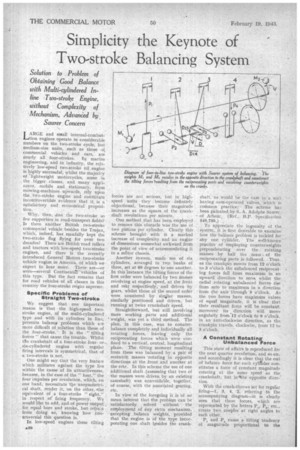
With the crank-throws set for regular firing-1, 3, 4, 2, referring to the accompanying diagram—it is clearly seen that these forces, which are represented •by the letters 135, P2, etc., create two couples at right angles to each other.
P, and P. cause a tilting tendency of magnitude proportional to the distance between the points of application of the two ,forces, whilst P2 and P, cause a further tilting moment proportional, to their distance apart. Therefore, the resultant moment of P1 and P4 (indicated at D1, A) is greater than that of P2 and P„ (D2„) at right angles and the resultant of these (D) is at an angle IP to D1, 4. Completely to balance this tilting moment, which, as has been shown; is of constant magnitude and rotates at crankshaft speed but in,the opposite direction, the two 'counterweights M, and M2 are suitably mounted on the
ends of the camshaft at angle Ye, as indicated, to the crank throws of cylinders 1 and 4. Obviously the masses of these counterweights are different for every different engine, being dependent upon the weights of the reciprocating parts, the distances between cylinder axes, their positions on the camshaft and so forth. Where tht camshaft is mounted in relation to the crankshaft is implied by the inventor to be of minor importance, also it is claimed that the tilting moments due to out-of-balance forces of the second order, can be
reduced to zero or to negligible value. ' We are not in full agreement with the inventor about the former matter, because as the axis of the camshaft hetomes remote from that of tfie crankshaft so is the tilting moment converted to a rocking tendency instead of being counteracted. Ideally the counterweights M, and M2 should revolve about the crankshaft axis.
Unquestionably, however, the attractions of the scheme are considerable in view of the simplicity and very minor nature of the few additional parts required solely for balancing.