


INTERESTING CRANKSHAFT CONSTRUCTION.
Page 32
If you've noticed an error in this article please click here to report it so we can fix it.
A Résumé of Recently Published Patents.
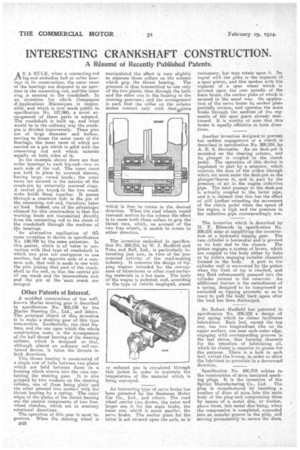
AS A RULE, when a connecting-rod big-end embodies ball or roller bearings in its construction, the outer races of the bearings a,re disposed in an aperture in the connecting rod, andithe inner ring is secured to the crankshaft. In an invention for which Compagnie d'Applications Mncaniques is responsible, and which ia now made public in specification No. 187,960, a novel arrangement of these parts ia adopted. The crankshaft is built up, and what would be in the ordinary way the crankpin is divided transversely. These pins are of i.arge diameter and hollow, serving to house the outer races of the bearings, the inner races of which are carried on a pin which is solid with the connecting rod and which extends equally on both sides of it.
In the example shown there are four roller bearings to each big-end—two cm each side of the rod. The inner races are held in place by screwed sleeves, baying large, round heads; the enter races are secured in the interior of the crank-pin by externally screwed rings. A Central pin keyedi to the two crank webs holds them together. It passes through -a clearance hole in the pin of the connecting rod and, therefore, takes nb'haad. Indeed, one of the advantages claimed for this construction is that the working loads are transmitted directly from the connecting rod to the cheek of the crankshaft through the medium of the hearings.
An alternative application of the same nivention is shown in specification No. 190,700 by the same patentees. In this patent, which is of value in connection with that type of crankshaft in which two pins are contiguous to one another, but at opposite ends of a common web, that webis made in one with the pins joining that part-of the crankshaft to the rest, so that the central pin of one crank and the intermediate web and the pin of the 'next crank are integral.
Other Patents of Interest.
A modified construction of the wellknown Marles steering gear is described in specification. No. 209,139 by the If/larks Steering Co., Ltd., and others. The principal object of this, invention is to make a steering gear of this type irreversible. Incidentally, the chief feature, and the one upon which the whole construction rests, is the arrangement of the ball thrust bearing-of the steering column, which is designed so that, although almost an ordinary self-contained device, it takes the thrusts .in both directions.
This thrust bearing is constructed of a single row of balls between two plates which are held between faces in a housing which serews into the case containing the steering gear. It is also gripped by two washers on the steering column, one of them being plain and the other pressed into contact with the thrust bearing by a spring. The outer edges of the plates of the thrust bearing are the central components of two freewheel clutches, which act in contrary rotational directions.
The operation of this gear is most ingenious. 'When the steering wheel is 1348 manipulated the effect is very slightly to separate those collars on the eolumn which grip the thrust bearing. The pressure is thus transmitted to one only of the two plates, then through the balls and the other one to the housing in the steering gearcase; and the arrangement is such that the cellar on the column
makes contact only with thatP late
-S which "is free to rotate in the desired direction. When the road wheels would transmit motion to the column the effect is to cause both these collars to grip the thrust race, which, on account of the two free wheels, is unable to rotate in either direction.
The invention embodied in specification No. 209,214, by W. J. Hadfield and Tnke and Bell, Ltd., is particularly interesting just now, in view of the pronounced activity of the road-making industry. It concerns the design of tipping wagons intended for the conveyance of bituminous or other road-surfaeing materials in a hot State. The body of the wagon is jacketed, and, according to the type of vehicle employed, steam
or exhaust gas is circulated through this jacket in order to maintain the temperature of the material which is being conveyed.
An interesting type of servo brake has been patented by the Sunbeam Motor Car Co., Ltd., and others. The road wheel carries two drums, the outer and larger one is for the main brake, the inner one, which is much smaller, the servo brake. The anchor plate for the latter is not secured upon the axle, as is
customary, but may rotate upon it. Integral with the plate is the segment of a.spur pinion, and this meshes with the segment of a spur wheel which is pivoted upon the cam spindle of the main brake, the archer plate of which is secured in the usual way. On application of the servo brake its anchor plate partially rotates, and operates the main brake through the medium of the segments of the spur gears already mentioned. It is worthy of note that this brake is equally effective in both direc tions.
Another invention designed to prevent ton' sudden engagement of a clutch is described in specification No. 209,204, by A. E. S. Seccombe. An air dash-pot is mounted on the steering column, and its plunger is coupled to the clutch pedal. The operation of this device is regulated in part by a Setscrew, which controls the area of the orifice through which air must enter the dash-pot as the plungeraleaves it, and in part by the pressure of air in the engine induction pipe. The inlet passage to the dash-pot is actually coupled to the latter pipe, and it is claimed that this.has the effect of still further' retarding the movement of the clutch pedal when the speed of the engine is high and the pressure in the induction pipe, correspondingly low.
The invention which is described by M. F. Edwards in specification No. 209,231 aims at simplifying the construction of a hydraulic tipping gear. The .ranl cylinder is horizontal and is pivoted
at its butt end to the chassis. The piston engages a system of levers, which are coupled to the body either by links or by rollers engaging suitable channels formed in the body. A port in the cylinder wall is uncovered by the piston when the limit of tip is reached, and any fluid subsequently pumped into the cylinder returns to the reservoir. An additional feature is the embodiment of a spring, designed to be 'compressed or extended as tipping proceeds, so as to react to pull the body back again after the load has been discharged.
Sir Robert Hadfield has patented in specification No. 209,233 a design of leaf spring which he claims facilitates lubrication. Each leaf, except the top one, has two longitudinal ribs on its upper surface, one near each outer edge,' engaging with corresponding grooves in the leaf above, thus forming channels for the retention of lubricating oil, which he claims is superior to grease for the purpose. There is a hole in each leaf, except the lowest, in order to allow the lubricant to percolate in a downward direction.
Specification No. 206,319 relates to the construction of mica insulated sparking plugs. It is the invention of the Sphinx Manufacturing Co., Ltd. The plug is manufactured by inserting a. somber of discs of mica into the main body of the plug-and compressing them by means of a metal disc, or washer, above them, this metal disc being, when the compression is completed, expanded into an annular groove in the plug, and serving permanently to secure the discs.