


Fr m Drivers &Mechanics
Page 20
Page 21
If you've noticed an error in this article please click here to report it so we can fix it.
TEN SHILLINGS WEEKLY is paid for the best communication received, and one penny a line of ten words for anything else published, with an allowance for photographs.
Send us an account of any special inczdent of your work or experience. If suitable, we will edit yner rotes, suPPly a sketch when required, la and pay you for everything puviished. Mention your emPloyer's name,
in confidence, as eindence of good foul.: Address to The3 Editor, Tile
COMMERCIAL MOTOR, Rosebery Ave,a‘e, London, E.0 Light Up Your Lamps At
6.18 on Thursday ; 6.20 on Friday ; 6.22 on Saturday ; 6.27 on Monday ; 6.28 on Tuesday ; 6.30 on Wednesday.
See That Your Road-wheels Run True.
[1442] " N" (Cardiff) writes :—" In the garage where I am employed we attach no little importance to the matter of general alignment of vehicles before sending them out after an overhaul. I have, therefore, been much interested in the letters and din.
grains published lately in your 'U. and columns showing the different means adopted, both in the factory and garage, for testing chassis and road-wheel alignment.
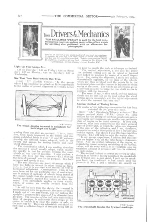
" The contribution which I am sending describes the method I myself usually adopt, which enables me quickly to test for parallel running the roadwheels of any type of machine. I also enclose a sketch [We have had this redrawn.—Eo.] showing the form of trammel I use for the purpose. It is both accurate and speedy in use.
"The tool possesses one great advantage which I have nor hitherto noticed in other lining-up trammels, in that it is provided with vertical as well as horizontal adjustment. Consequently, when it has once been set for any particular size of road-wheel, one is certain of eachipair of wheels being tested at the correct height from the ground in all such cases, having previously marked two points on their diameter. This particularly applies to front wheels, which, of course, are usually inclined from the vertical.
"As will be seen from the sketch, the trammel is accommodated with two pedestals, the bases of which I made out of two gear-blanks, and for making the uprights I procured two pieces of in. diameter iron gas-pipe. The crass-bar of the tool, also made from a piece of gas-pipe, is sufficiently down-swept at its centre to enable it to clear the engine or axle, as the case may be. There are adjustable rods fitted at each end, a sufficient length of straight being left on
n2 the pipe to enable the rods to telescope as desired, " For vertical adjustment, a rod also fits inside the pedestal tubing and can be raised or lowered and locked in position by means of a small fingerlever. For testing the alignment, I mark two points, diametrically opposite, on the rims of the wheels, which are then revolved until the points lie in the horizontal plane and the trammel is adjusted to those marks at the front. The wheels are afterwards given a half-turn in order to bring the rear chaiii marks in position with the trammel. " The error, if any, is then noted, and the machine should not be sent out on the road unless the wheel setting agrees reasonably with the initial adjustment to which the trammel had been set."
Another Method of Timing Valves.
The -sender of the following communication has been awarded the 10s. prize this week.
[1443] " CL." (Newton-le-Willows) writes :—" The unique method which W.J.M.' (letter No. 1434) utilizes for the timing of overhead mushroom-valves is certainly very ingenious, and enables one particular class of engine to be timed correctly. It does not, however, take into consideration the more general type of power unit, in which the valves are disposed at the side of the cylinders, and I am, therefore, prompted to send a description of how I myself time such an engine. The sketch I send [We have had this redrawn.—En.] will help to make the matter clear.
"In my garage experience, I seldom find that one gets an engine with all the valve-tappet clearances equal. Now the perfect balancing of the engine, as regards the correct opening and closing of the various valves, will do away with a lot of vibration, also the maximum amount of pressure will thus be obtained on each piston.
"The method I adopt, to correct any errors in valve. timing is as follows : having assembled the crankshaft and flywheel only, as per sketch, I pack up the crankcase level, the crankshaft is then turned until the journals of Nos. 1 and 4 cylinders are exactly on
t.op. This position is obtained by menus of a square held to the side of the crank-web and a spirit-level placed on top of the blade. Haying got. this correct, I fasten a pointer, made out of thin metal sheet, on top of the crankcase to overlap the flywheel, and then scribe a. line on the wheel rim opposite the pointer and mark it 1 and 4 top. " The next operation is to revolve the crank until throws Nos. 2 and 3 are on top, the correct vertical position again being obtained by means of the square and spirit-level. The cylinders are then placed in position and the engine built up before proceeding further. I then turn the crankshaft until No. 1 exhaust valve closes. This should take place shortly after the dead centre. A chalk mark is put on the flywheel opposite the pointer, and the crank tumid until No. 4 exhaust closes, when the flywheel should again be marked where the pointer overlaps. "Now, any difference between the timing of No. 1 and No. .1 markings, with relation to the pointer, can be altered by turning the camshaft backwards or forwards one or two teeth as required. I next proceed with No. 1 and No. 4 inlet in the sarne way as the exhaust, and, with but a little adjustment of the tappets, inlet valves No. 2 and No. 3 will fall in with the correct timing of the engine. The position of the valves should be taken both open and closed. " With regard to the ignition, I generally adyanco this about 10 min., mark the flywheel and turn the engine, until the line comes up to pointer. I then remove the contact cover on the magneto and retard fully ; the contact. points should then be just about to break.' When these details are closely followed, there will be little difficulty in starting up, and steady running of the engine will also ensue."
Useful When Your Machine is Bogged. [444] " H.B." (Broodey) mites :—" In a recent
letter No. 1428] to the ` U. and pages, the writer explained the reason for always carrying a jock in the tool kit of a steam wagon, .Aecoeding to the registration number shown in the included photog,rapin I should judge the machine to be about three years old. I am surprised at there being no jack aboard, as without doubt there was one when the wagon was new.
" Apart from this, I should like to explain a method I use when the steam-wagon I drive is bogged, which happens more times than I care to record; it is engaged in hauling material to building sites in the country.
" The idea is always to carry a hauling chain about 6 ft. or 8 ft. long, made with 4 in. or 4 in. links, having a ring and hook at opposite ends, and a piece of timber 1 ft. long by 6 ins. square. The outfit is useful in more ways than the one explained.
" When using thechain for getting a wagon out of difficulties, pass it about twice round the felloe of
the wheel, as shown in the accompanying sketch— [We have bad this redrawn.---Elen—and insert the wood block at an angle in the slack of the chain near the wheel rim. Should the other road .wheel be on hard ground, use a small quantity of oil on the tire to make it slip. Make sure that the engine has plenty of power, and the wagon will then not have much trouble in lifting itself out.
" This method I have often resorted to on traction engines, and during the three years I have been in my present job I have never resorted to the jack, which, however, I always carry."
[Absence of a Lire brIke S appareaLly assurnod_to
Reboring Worn Tappet-holes with a Bench Drill.
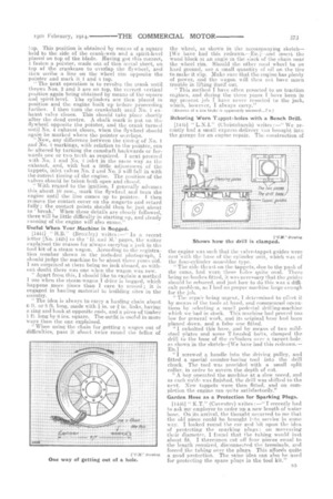
[1415] " L. N.I." (Christchurch) writes:—' We recently had a small express-delivery van brought into the garage for an engine repair. The construction of the engine was such that the valve-tappet guides were east with the base of the cylinder unit, which was of the four-cylinder monobloe type. " The side thrust on the tappets, due to the push of the cams, had worn these holes quite oval. There being no hushes fitted, it. was necessary that the guides should be rebored, and just how to do this was adifficult problem, as I had no proper machine large enough for the job. " The repair being urgent, I determined to effect it by means of 1:he tools at hand, and commenced operations by selecting a small pedestal drilling-machine which we had in stock. This machine had proved too low for general work, and its original base had been planed down, and a false one fitted. " I unbolted this base, and by means of two mildsteel plates and some T-headed bolts, clamped the drill to the base of the cylinders over a tappet-hole, as shown in the sketch--[We have had this ED.] " I screwed a handle into the driving pulley, and fitted a special counter-boring tool into the drill chuck. The tool was provided with a small split collar, in order to govern the depth of cut.
" A boy operated the machine at a, slow speed, and as each guide was finished, the drill was shifted to the next. New tappets were then fitted, and on completion the engine ran quite satisfactorily."
Garden Hose as a Protection for Sparking Plugs.
[1446] " K.T." (Coventry) writes :—" T recently had to ask my employer to order up a new length of water hose. On its arrival, the thought occurred to me that the old piece could be brought into service in somo way. I looked round the ear and hit upon the idea of protecting the sparking plugs : on measuring their diameter. I found that the tubing would just about fit. I thereupon cut of four pieces eonal to the length reouired, disconnected the terminals, and forced the tubing over the plugs. This affords quite a good protection. The same idea can also be used for protecting the spare plugs in the tool kit."