


Patents Completed.
Page 20
If you've noticed an error in this article please click here to report it so we can fix it.
Complete specifications of the following patents will be sent to any address in the United Kingdom b7 the Sale Branch, Patent Office, Holborn, W.C., upon receipt of eightpence per copy.
A Compound Radiator.
J. Brundrit, No. 226, dated 3rd -January, 1912.—The object of this invention is to obtain the efficient cooling of the circulating water of the engine. An ordinary radiator is used fur the circulating water, and the tubes of the radiator are exposed to the air to help the necessary cooling. These tubes are cooled in their turn by a separate water supply which circulates in additional radiators • having ordinary air-cooled tubes arranged at the back and front of the engine-water radiator. Any arrangement of tubes may be used, the essential feature of the invention being that the .engine circulating water is cooled by -other water as well as by air.
A Two.-stroke Engine.
Sir Charles Stewart Forbes, No. 25,266, dated 13th November, 1911.—In this engine a long trunk piston is used, and a fixed piston is arranged inside it. The space above the trunk piston, which would normally be the combustion space, is here used as a pump, air and an explosive mixture being drawn into it through ports about the middle of its length. The 'mixture is compressed on the upward stroke of the trunk piston. and is transferred to the space inside the trunk piston above the fixed piston. It is there further compressed on the outward stroke, and is ignited by a plug mounted in the outer cylinder casing. This is arranged to come opposite one of the transfer ports at the end of the second compression stroke. The exhaust ports are arranged at the opposite ends of the respective cylinders from the inlet ports.
Electric Power-transmission.
The Macfarlane Engineering Co., Ltd., No. 2817, dated 3rd February, 1912.— Practically all that this variable speedgear consists of is two continuous-current electrical machines which have their armatures connected together in series. What the inventor calls the primary machine is a dynamo, and similarly a motor constitutes what is called the auxiliary machine. There are wiring-arrangements by which the dynamo becomes the motor, and the motor • the dynamo, according to the speed.
The primary machine has its field magnets combined in one with the field magnets of the auxiliary machine; both these are coupled to the driving shaft of the driving engine. The armature of the primary machine is coupled to the variable-speed shaft, the armature of the auxiliary machine being held stationary,. The exciting current necessary is carried to the field-magnet coila through slip rings, and may be varied by resistances or by shifting the brushes. In addition
to the exciting windings of the field magnets, there is another winding on the poles of the auxiliary machine which is in series with the main circuit, and is arranged to oppose the exciting winding of its own machine. The result is that while the two exciting windings tend to produce a current in the main circuit, say in the positive direction, the current in the series winding will oppose this. As an example, the variable-speed shaft may be going slower than the engine, whereupon, if the exciting windings have the full current passing through them, the primary field magnets will set up a current in the main circuit, say in the positive direction. As the exciting winding or magnet on the auxiliary machine is acting in the same direction, the current will increase until the series winding overpowers and reverses the magnetie field of its own machine, so setting up a current in the main circuit almost equal to the current in the primary field magnets, and opposite to it. The primary machine will thus be acting as a dynamo, and the auxiliary machine as a motor, returning power to the origins. But the torque of the engine will be conveyed to the variable-speed shaft, and will be proportional to the main current and the current in the primary field magnets multiplied together.
A Strengthened Tire.
A. Steinhauser, No. 8374, dated 9th April; 1912.—There is an extra annular cushion inside this tire which ia ester nally of similar construction to other tires. The cushion rests on the outermost face of the inside of the cover, and is shaped in section something like a bifurcated rivet. The legs of the bifurcation rest in a ring which passes round the rim inside the tire ; this keeps the legs of the cushion off the side walls of the cover by virtue of its having wedge-shaped tongues which bear in between metallic pieces fitting over the inside of the beading of the cover. The ring which supports the cushion is split in three places, and is held together by slotted plates which allow of a certain amount of play.
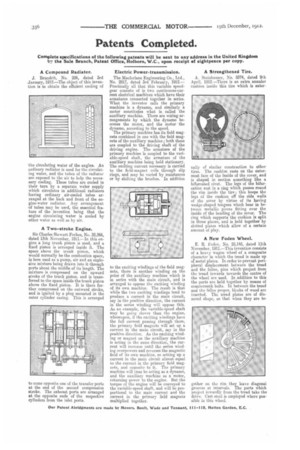
A New Foden Wheel.
E. It. Foden, No. 25,145, dated 11th November. 1911.—This invention consists of a heavy wagon wheel of a composite character in which the tread is made up of metal plates. In order to prevent peripheral displacement between the tread and the felloe, pins which project from the tread inwards towards the centre of the wheel are used, In addition to this the parts are held together by means of countersunk bolts. In between the tread and the felloe proper, blocks of wood are inserted. The tread plates are of diamond shape, so that when they are to
gether en the rim they leave diagonal grooves at intervals. The parts which project inwardly from the tread take the drive. Cast steel is employed where possible in this wheel.