


Patents Completed.
Page 20
If you've noticed an error in this article please click here to report it so we can fix it.
DAIMLER-MOTOREN-GEBELLSCHAFT, No. 5394, of 1915, dated under International Convention 28th April, 1914.—In the arrangement described in this specification the oil is supplied by a pump at the bottom of• the crank .chamber to the in tenor of the camshaft. The camshaft itself is provided with radial holes in each bearing and in each cam, so that a continuous -flow of oil outwards from the shaft is obtained at each of these points.
The camshaft and its driving gear are all contained in an oil-tight casing which receives the outwardly flowing oil and retains a certain quantity as an oilbath. The overflow may be arranged to pass back to the crank chamber through a hollow vertical shaft carrying the bevel gears for driving the camshaft.
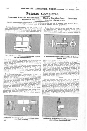
H. DE BOISCHEVALIER and L. CHEVROLET, No. 15,562, dated 29th June, 1914.—The special feature of this radiator is that the tubes and radiating fins are all stamped out of one sheet of metal. , One end of the sheet has a small flange formed, and it is then, bent over at the dotted lines to form a flat tube. The other end of the sheet is cut as shown at the full lines and bent at the dottedtlines, the bent-up portions forming the radiating fins. The whole of this end of the sheet is then bent round to lie against the tube, and the complete radiator
formed by assembling a sufficient number of these tubes together and dipping them in a solder bath in the usual manner.
It will be seen that the radiating fins are formed double at each edge of the tube for joining the tubes together, and single at the intermediate parts. Top and bottom tanks are fitted in the usual manner. ROBERT BOSCH, LTD., No. 20,928, dated 10th June, 1914.— In this starting gear a special free wheel is used to prevent wear while it is not in operation. When the roller construction is used, small bell-crank levers are arranged to hold the rollers at the bottom of their respective recesses. These
levers are operated by a coned sleeve sliding on the shaft.
The motor circuit is controlled by an electro-magnetic switch, and the switch is inter-connected with the coned sleeve. ,When it is desired to start the engine, the switch beside the battery is closed to complete the circuit of the magnet. This automatically closes the main switch for the motor, and at the same time withdraws the coned sleeve. The bell-crank levers are thereby moved backward and the rollers are free to ride into their engaging positions, so that the motor drives the engine. When the engine fires, all the parts are returned to their original positions by opening the switch in the magnet circuit.
ELECTRIC IGNITION CO. (1913) LTD., AND A. Cox, No. 13,432, dated 2nd June, 1914.—In this carburetter the control is effected by a sleeve which slides downwards over the jet and across the outlet for throttling. A needle on this sleeve fits inside the jet and adjusts the opening of it to the throttle' opening. According to this invention the needle is adjust-, ably mounted in the sleeve on a Bowden wire control. The ordinary nipple adjustment of the Bowden wire allows the main or primary adjustment of the needle in the jet by hand,but if a weaker or stronger mixture is temporarily required,the necessary movement of the needle relatively to the con-. trolling sleeve is effected by the Bowden wire control from the. driver's seat.