


OVERHAULING THE ATKINSON.
Page 20

Page 21
Page 22
Page 23
If you've noticed an error in this article please click here to report it so we can fix it.
No. 14. —With a Vertical Boiler and an Undertype Engine great Accessibility to Vital Parts is Afforded. The Work of Dismantling and Reassembling.
THE STEAMER and the petrol vehicle each presents its own peculiar problems to the user, and this is no less true in connection with overhauling such machines than it is with regard to any other aspect of their use. It might be claimed for the petrol vehicle that it is less trouble to overhaul because it does not have v, boiler. On the other hand, the steam vehicle, or at least the undertype, has the advantage of being minus a gearbox. In fact, the boiler apart, the steam wagon is perhaps one of the simplest form sof transport vehicle available, and this is particularly apparent when we come to consider the best means of overhauling it.
The designers of the Atkinson might almost have been. thinking along these lines when they first laid down the drawings for this, by now well-known, steam wagon, and above all have they considered in this regard the problem of overhauling the boiler. . ,
First Steps in the Overhaul.
The preliminary steps in connection with the overhaul of -this type of lorry are naturally the same as for any other kind. The first thing to do is 'to remove the body, setting it at one side on trestles, where it is conveniently accessible for cleaning and either entirely repainting, or being touched up hare an-a there, as may be necessary. When this step is taken, someone may be set the task of cleaning the chassis and individual components externally, so far as they are accessible for this purpose, and, as a preliminary to that work, the driving chain ought to be removed,
all the loose dirt and external grease brushed or scraped off, and the chain then set to soak in paraffin preparat4y to a more thorough cleaning at a later stage in the proceedings.
While this is going on, the roof of the driver's cab must be removed M. order to render the boiler accessible. The boiler funnel must then be taken off. It will be found on examination to be secured to the top cover of the steam generator by .means of four bolts. The shield or apron plate, which, in effect, forms the front of the driver's cab, should be removed next, thus exposing the whole of the boiler and accessories. Uncouple the steam and exhaust pipes, and remove the top cast cover of the boiler, taking with it the superheater coil. All this is, in a sense, merely clearing the way in. order -to get at the main essential parts of the boiler itself.
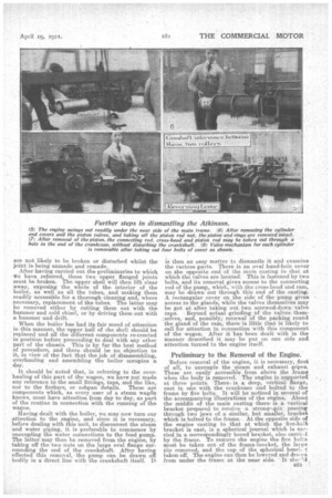
The boiler of the Atkinson, as most of our readers will be aware z is of the vertical type, with a central firebox containing a number of short water tubes lying almost horizontally in layers one above the other, each alternate layer of tubes being set at right angles to the one below. The inner firebox and the lower half of the outer shell are welded together to form one piece, which rests on the frame of the chassis. The upper edge of the lower part of the shell and the top of the firebox are flanged, and to these flanges is secured, by means of a large number of setscrews or studs, the upper half of the boiler shell, the necessary steam and water-tight joint between them being made by graphite-covered asbestos rings, which are practically permanent and
are not likely to be broken or disturbed -whilst the joint is being unmade and remade.
After having carried out the preliminaries to which ike have referred, these two upper flanged joints must be broken. The upper shell will then lift clear away, exposing the whole of the interior of the boiler, as well as all the tubes, and making them readily accessible, for a thorough cleaning and, where necessary, replacement of the tubes. The latter may be removed either by cutting them out with the hammer and cold chisel, or by driving them out with a. hammer and drift.
When the boiler has had its fair mood of attention in this manner, the upper half of the hell should be replaced and all the different components re-erected in position before proceeding to deal with any other part of the chassis. This is by fax the best method of procedure, and there should be no objection to it, in view of the fact that the job of disassembling, overhauling and assembling the boiler occupies a day.
It should be noted that, in referring to the overhauling of this part of the wagon, we have not made any reference to the small fittings, taps, and the like, nor to the firebars, or ashpan details. These are components which, as every user of a steam wag& knows, must have attention from day to day, as part of the routine in. connection with the running of the wagon.
Having dealt with the boiler, we may now turn our attention to the engine, and since it is necessary, before dealing with this unit, to disconnect the steam and water piping, it is preferable to commence by uncoupling the water connection's to the feed pump. The latter may then be removed from the engine, by taking off the two nuts an the large oval flange surrounding the end of the crankshaft. After having effected this removal, the pump can be drawn off bodily in a direct line with the .crankshaft itself. It is then an easy matter to dismantle it and examine the various parts. There is an oval hand-hole cover
the opposite end of the main casting to that at which the valves are located. This is fastened br two bolts, and its removal gives access to the connecting rod of the pump, which, with the crass-head and ram, may be drawn out through this end of the casting. A rectangular cover on the side of the pump gives access to the glands, while the valves themselves may be got at after, taking out two screwed-down valve caps. Beyond actual grinding of the valves them:selves, and, possibly; renewal of the packing round the gland of the rain,there is little that is likely to call for attention in Connection with this component of the wagon. After it has been dealt with in the manner described it may be put on one side and attention turned to the engine itself.
Preliminary to the Removal of the Engine.
'Before removal of the engine, it is necessary, first of all, to uncouple the steam and exhaust pipes. These are easily accessible from abeve the frame when the body is removed. The engine is supported' at three points. There. is a deep, vertical flange, east in one with the crankcase and bolted to the frame by five bolts. It will be noticed in several .of the accompanying illustrations of the engine. About the middle of. the main casting thereis a Vertica,1 bracket prepared to receive a strong—pin passing through two jaws of a similar, but smaller, bracket which is bolted to the frame. At the opposite side af the engine casting to that at which the flve-bolt bracket is cast, is a, spherical journal which is carried in a correspondingly bored bracket, also carriA by the frame. To remove Ihe engine the five be] (s must be taken out of the frame-bracket, the large Pin removed, and the cap of the spherical beari. taken off. The engine can then be lowered and draTya from under the frame at the near side. It sho-lil
be laid aside on trestles for independent. overhaul. As a, preliminary to this the cylinder ,covere may be removed as well as the large hand-hole cover at that end of the crankcase opposite to the cylinders, and also the two covers for the camshaft. The next o.peratien is the removal of the pistons. •
The procedure here differs according to the type of engine. In the older models with the plain pistons, it is merely necessary to remove the nut on the end of the piston rod, and the piston, with a little manipulation, can be taken out at the rear end of the cylinder. In the new Uniilow type, there is a valve carried by the piston itself, and in order to get at the nut on the end of the piston rod this valve,' which is retained by three nuts, must first be removed. After the pistons have been taken out, the caps of the big-ends of the connecting rods should be detached, when it will be found possible to take out the connecting rods, cross-heads and pistons through the large hole in the end of the crankcase without disturbing the crankshaft itself, if it be thought unnecessary to remove this component. The detail method of overhauling the connecting rod, gudgeon pin, piston rod, pistons' etc., need not be dealt with. The operations present no special difficulty, nor are there any unusual features about their construction which call for comment.
Examining the Valve Gear.
The valve gear parts require little more than examination. This, fortunately, may easily be accomplished as the complete gear for each cylinder is accessible after withdra,wing the camshaft, by taking off the four nuts of the casting through which the valve rods protrude. The whole of the valve gear can then be withdrawn and exposed for examination, as is shown on one of the accompanying illustrations. The bearing surfaces of the valve rods, tappet rods, and so on, are so generous that it is quite an unusual thing for any renewals or repairs to be needed in connection with these parts, while the valves themselves are actually hardened steel balls such as are used in ball bearings. They are, in the first place, hammered on to narrow mild steel Beatings, thus forming their own beds, which rarely become worn or otherwise depreciate.
In the event of wear having taken place in the main bearings for the crankshaft,--these are carried in bracket bearings bolted to the cheeks of the crankcase, and may be separately removed after detaching six nuts in each case. The crankshaft may also be withdrawn through the cavity left after removal of these covers and it should be noted that the timing wheel, which is on the crankshaft, is marked so that it automatically registers with the camshaft wheel, and there is no necessity/to consider the question oftiming the engine. That, at least, is the case with the new Uniflow Atkinson engine. In the old type a little more circumspection necessary in dealing with the; valve gear, and, in order to assist users who have the standard type of engine with separate valves for steam and exhaust, we publish the accompanying timing diagram, by the aid of which they should be able to re-erect this portion of the engine to their own satisfaction.
The Timing of the Engine.
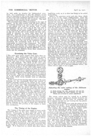
The timing of the older type engine is more easily performed after it has been replaced under the chassis. Presumably, by that time, all play in the reversing gear and connections will have been taken up, and there is, therefore, no need to call attention to the necessity for this being done before any alteration or correction of the timing is effected. The makers of the engine supply a chart by which the timing may be checked. This should be obtained from the offices a.nd pitmed up in such a position that it can easily be referred to during the operation of timing. It is important to obtain this chart before B26 beginning work, as it is then less likely to be soiled by -handling. Remove the gearcase cover and also those which give access to the engine stuffing-boxes. Place the reverse lever in the g Forward Start" position and measure how far the ends of the camshaft stand out beyond the faces of the bevelled pinions; if these distances, as measured, do not correspond with those given in the chart, adjust them by means of the corresponding screw couplings on the rods which connect the control levers to the inner shafts. Next get an assistant, using a, spanner on the chain pinion nut, to turn, the engine in the same way as it would revolve to drive the wagon forward. Watch the exhaust valves and, when one is being lifted, observe the clearance, between the other valve and its stem; in erder to insure proper setting the clearance should be 10-1,000 in. If there is too much clearance, the tappet may be drawn. out a little; if the clearance is not sufficient, shorten the tappet accordingly. With the assistant still turning the camshaft, note when the piston reaches the end of its stroke and / make a mark on the piston red in line with the gland. Continue turning the crank until the piston is I in. from the end of its stroke and moving towards en& the exhaust valve for that end of the cylinder should then open. If it does not open correctly, adjust by slacking off the bolts (1) which join the cam quadrants (2) and (3), afterwards turning quadrant (2) until the necessary adjustment is effected. To ascertain when the valve is just open, hold it between finger and thumb and keep trying to revolve it as the engine is turned ; while it is seated it is difficult—almost impossible—to move it, but, so soon as it is lifted, it will revolve quite easily. If all the clearances between valves and tappets are correct, it is only necessary to time one out of the four exhaust valves ; the others will be right if one is right.
• The steam valves may be tested in a, similar manner; necessary adjustment should, however, be made by slacking off the belts (4) coupling. the bevel pinions (5) and (5) and turning the top pinion (5) to obtain adjustment.
The steam valve should open with the piston at the beginning of its stroke. It is advisable to check over the timing of all four steam valves independently. After timing, the engine should be. tested under steam before replacing the main driving chain.
One of the advantages of the steam wagon, particularly of the type we are now discussing, is that it is conveniently arranged in units which may-13e overhauled either independently or together with the wagon as a whole. We have already pointed out that, as regards the boiler, this is best treated as a complete operation and finished independently in one day. The same remark might apply to the engine, and it is preferable to deal with this unit in the same way as the boiler, that is to say, dismantle, overhaul, and reassemble before turning attention to the other features of the chassis.
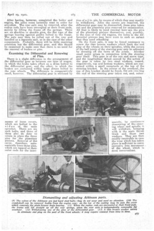
After having, however, completed the boiler and engine, the axles come naturally next in order for attention. The rear axle may be removed, after the radius rods have been uncoupled at their front ends, merely by lifting the frame off the springs. There are no shackles or shackle pins, the flat tops of the s rings bearing against guides bolted to the frame. The axle may then be rolled out of the way and handled as a separate unit, as in the case of the other components. Probably, there will be little requiring attention but the differential gear, and this should be examined to make sure that there is no need for the renewal of bushes or pins.
Examining the Differential and Renewing.
of Pins.
There is a slight difference in the arrangement of the differential gear as between one type of wagon, in which the! brake takes effect on a drum bolted to the differential gear, and the other, in which the brakes are contained within large drums bolted to the rear wheels. The difference is comparatively small, however. The differential gear is enclosed by tion of a in. pin, by means of which they may readily be withdrawn. After the covers are removed, the differential gear may be dismantled, these pins taken out and the planetary pins removed for examination. Allthat is likely to need renewal herfeare the pins of the planetary pinious themselves, and, possibly, in the case of very old wagons, the holes in the differential pinions may have worn to such an extent that they need rehashing.
On the front axle, it. may be found necessary to renew the thinbronze washers which limit the-end play of the wheels on their spindles, while the covers of the ball joints of the steering`gear may be adjusted
by dressing off the faces Of. the joints. Another small point arises in connection with, the steering gear itself. This gear is of the nut and screw type, and the longitudinal thrust caused by the action of the gear is taken by two steel washers, named, respectively, top and bottom washers, 'which are contained within a small receptacle at the top of the steering bracket. In the course of the overhaul, the cap of this bracket should be freed, the pin COM ling the end of the steering gear ta.ke.i . out, and, subee