


Rubber Rear Suspension
Page 94
If you've noticed an error in this article please click here to report it so we can fix it.
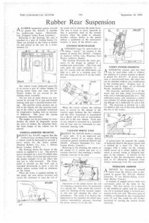
ARUBBER suspension system covered by patent No. 816,071 is suitable for tandem-axle bogies. (Metalastik, Ltd., Evington Valley Road, Leicester.)
Referring to the drawing, the axle is attached to a pair of trailing beams (1). These are pivoted to the frame at points (2) and joined at the rear by a crossmember (3).
The vehicle frame (indicated generally at 4) carries a pair of rubber bushes (5) having metal inner and outer sleeves. Similar bushes (6) are carried by the trailing beam assembly.
The two sets of outer sleeves are connected by tie-rods (7) at top and bottom making each pair a parallel-motion linkage. The parallel action permits rise or fall of the wheels, but the torsional loading of the rubber is gradually reinforced by compressive loading with an increase of deflection. This gives the system progressive characteristics.
The bushes can be pre-loaded by turnbuckles (8) which lie diagonally across the pairs of bushes. By adjusting these, the static height of the vehicle can be altered.
INERTIA-ASSLSTED BRAKING
PATENT No. 814,993 suggests that the forward force resulting from braking a vehicle could be harnessed to provide a servo action for the brake system. (Dunlop Rubber Co., Ltd., 1 Albany Street, London, N.W.I.)
The drawing shows the layout of the system as applied to a car. The driver's seat is mounted on a strut (I) which rides freely on rollers (2) at one end and carries the master cylinder (3) at the other; this end too is roller-mounted. The brake pedal is pivoted on the strut and is extended downwards to form a tail (4) which makes contact with an abutment on the frame.
When the brake is applied initially by the pedal, the seat moves forward and causes the abutment to meet the tail of the pedal and so increase the pedal force. The seat is made to move upwards so that it gravitates back to the normal position when the pedal is released. Another scheme shown in the patent utilizes a pendulum as the momentum member in place of the driver's seat.
STEERED SEMI-TRAILER
ASTEERED bogie for semi-trailers to reduce " cut-in" on corners is the subject of patent No. 814,821. (Taskers of Andover (1932), Ltd., Waterloo Iron Works, Andover, Hants.) The drawing illustrates the basic geometry of the design as applied to a tandem-axle semi-trailer. The front end rests upon the usual turntable (1). A pin (2), mating with the fifth-wheel, can slide in a slot in a rocking lever (3), this unit being pivoted at 4 on the trailer frame.
When the tractor corners, the rocking lever is moved by the change in the relative angle between the two vehicles, and the lever movement is transmitted via a thrust rod (5) and an intermediate lever (6) to the rear wheels. Each pair of rear wheels is mounted on a turntable and all four sets are connected by conventional steering rods.
VACUUM SERVO UNIT
PATENT No. 814,556 shows a vacuum servo unit. It is an improved and simplified version of an earlier device covered by patents numbered 549,622 and 549,693. (Clayton Dewandre Co., Ltd., Titanic Works, Lincoln.)
Referring to the drawing, the whole of the casing (1) is sealed and acts as a vacuum reservoir, thus enabling a smaller external reservoir to be used.
Operation of the pedal moves the rod (2), rocking a reaction lever (3) connected to a stirrup (4).. This works the control valve (5), shutting off the vacuum supply at one end and opening the other to atmosphere. The result is to destroy the depression in the chamber (6) which then receives atmospheric pressure thrusting the power piston (7) to the left. FODEN POWER STEERING
ASTEERING column and box that can be used either with or without the addition of a power cylinder is shown in patent No. 815,757. If power assistance is incorporated later, the extra unit can be attached without any modification to the existing parts. (Fodens, Ltd., E. Twemlow and S. Edge, all of Elworth Works, Sandbach, Cheshire.)
The manually operated part is of the worm and nut type using re-circulating balls and is indicated generally at I. The additional power unit comprises a piston and cylinder (2) which operates the steering linkage via a bellcrank (3) and a link (4). The drop-arm is pivoted on a pin (5) which is also one of the bolts that hold the box to the frame.
A piston-valve (6) controls the supply of hydraulic fluid to the power piston and is worked by a lever (7). The lever engages with a collar on_ the column which moves up or down slightly as the wheel is turned, owing to designed endplay in the column. A feature of the design is that the steering-box casing is said to be effectively protected from shocks emanating from the road wheels.
PERISCOPE MIRROR
A DEVICE for increasing forward A—k vision from the driver's seat is described in patent No. 8.15,134, (Society Glacauto, 52 rue Marius-Aufan, Levalloise (Seine), France.)
It consists of angled mirrors built into convenient parts of the body of the vehicle. The first mirror (1) is located in the dashboard region and the second one (2) is mounted under a forward projection of the cab roof. The extra zone of visibility is indicated by the cross-hatched area (3) and this could be still further increased by moving the second mirror forwards.