


SOME INTERESTING VALVE GEARS.
Page 28
If you've noticed an error in this article please click here to report it so we can fix it.
A Résumé of Recently Published Patents.
THE PARTICULAR importance and interest of specification No. 178,837, by Daimler-Motoren-Gesellschaft, lies not so much in the mechanieal contrivance to which it refers, but in the inferences which may be drawn from its matter, and the name of the company which is responsible for it. The application of the Diesel engine to a road vehicle is something which, must shortly become a matter of practical politics. Now this specification actually deals with a very small detail of a Diesel engine, namely, the control of the fuel inlet valve, and there is, in the specification itself, no actual reference to a motor vehicle, or any suggestion that the engine to which this particular mechanisim is to be applied will be used for propulsive purposes, whether of a road vehicle or of any other machine of that kind. There is only the fact that the drawing of the engine resembles a commercial motor vehicle engine very closely indeed, hut this small item, coupled with the name of the patentee, is, we think, significant. The invention, as we have mentioned, refers to a detail of the operating gear of the fuel inlet valve. These valves, state the patentees, must be located in the centres of the cylinders, one to each, which disposal has hitherto been accepted as necessitating the arrangement of the operating gear for the valves at equal distances apart, correspondingly increasing the complication and weight of the mechanism by which those gears are controlled. Reduction of weight being a special desideratum, the usual arrangement becomes a disadvantage on that account. In the present construction, the usual location of the valves is accepted as essential, but the cams and onerating gear for a pair of cylinders are placed close together midway between the cylinders, operating the valves through the medium of a rocker shaft and suitable levers.
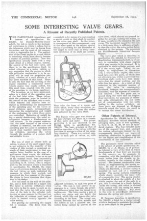
The use of steel or bronze balls as valves, in place of the usual poppet type, is not unknown to the majority of the readers of this journal, a prominent example of their employment in that connection being faniiliar in the case of a well-known steam wagon, the Atkinson. They have not, however, so far as we can at the moment recall, been successfully employed hitherto in any petrol engine. According to H. Colnot, who is responsible for the invention which is described in specification No. 186,891, the objection to all previous designs has been that the ball valves, as used, restricted the passages in which they worked, 'and prevented the free passage of the gases. He claims to have overcome that objection in his design.
The ball seats in the wall of the cylinder, and is held closed by a tappet rod.. The latter is entirely withdrawn when the valve is due to open, to such an extent that the valve can fall away quite clear of the hole in the cylinder wall, leaving an open passage for the gas from the induction or exhaust port, each of which is located exactly opposite the valve seating.
The gearing for operating the tappet rod is unusual. The drive from the crankshaft is by means of a rod coupling a special crank on that shaft to another on the valve gear shaft. As the latter, in consequence of this arrangement, runs at the same speed as the engine, special means of providing for the movement of the tappet to occur only on every alternate revolution of its shaft are needed.
They take the form of a worm and wheel which, every other revolution, remove the tappet rod, from the rocker arm actuated by the valve shaft.
The Bignan valve gear was shown at the last Olympia Car Slow on a chassis of that name and make. The patent governing it is now disclosed to the British public in specification No. 190,473. The basic principle is that of positive operation of the valves, with the provision of springs to allow of the necessary elasticity. There is a vertical camshaft to each pair of valves, or, with adjacent cylinders, to each two pairs of valves. The cam is very similar in appearance to a worm thread, the principal difference being that the thread is an endless one. The valve canies a pair of. rollers one above and one below the thread, whibh lifts and lowers the valve according to its 'form. The actual connection between the valve spindle rind the rollers is not a positive one, the rollers being carried by sleeves on the
valve stem, which sleeves are pressed to ether by springs. , causing the rollers, as it were, to embrace the thread of the cam worm. The movement caused lasi..the cam is a little more than is sufficient actually to close the Valve, the extra motion being absorbed by the springs. The patentees are Etablissements Industriels 'Jacques Bignam The valve gear which is described in specification No. 160,313, by Frankfurter Masschinebau Aktiengesellschaft, is of use only in connection with steam engines which may require to be reversed., It is applicable to multi-cylinder engines, and is of the rotary type. Taking, for example, its employment in connection with a four-cylinder engine, this valve need have only five ports, of which four are always in use, whilst in previous constructions eight ports have been necessary—four for ahead working, and the other four for astern. As a result of this reduction in the requisite number of ports, the valve is considerably. shortened, leakages are correspondingly climinshed, and the expense of construction reduced. The five ports are so spaced along the valve that its longitudinal movement, for purposes of reversing, puts, alternatively, the end ports out of communication with the ports leading to the various cylinders. As these ports are disposed at 90-degree intervals rOund the valve,. the result is to revere the steam distribution.
Other Patents of Interest.
Specification No. 179,959, by J. J. M. Bertrand, describes various methods a arranging units, each of four cylinders, to form 8, 12, 16, 20, 24 and 8 cylindered engines. The four-cylinder units' are of the opposed type, and, amongst the various advantages claimed for, the arrangements described are improved balancing, diminution in space. required for the engine and simplification of the construction of the crankshaft.
The pneumatic shock absorber which is the subject of patent specification No. 183,805, by J. A. Hea.ny, is of particular interest in view of the lines on which developments of that kind are running in this country, as, for example, in connection with the insulation of motor coach 'bodies from the chassis, as described recently in the -columns of this journal. The present construction aims merely at supplementing the spring action. In one of several constructions which are described, a circular casing is mounted on each end of a transverse spring. The casing contains something which closely resembles the inner tube of a pneumatic tyre.The spring shackle is" attachedto about the middle of a bar which couples the end of the axle to a pin, this is attached to a block floating inside the casing, and which is divided, from. contact with the casing by means of the pneumatic cushion. Any shock to the axle is accordingly distributed between the spring and cushion.
H. Ferguson describes, in specification No. 195,421, a hitch for t tractor plough which is designed to maintain the plough at an even depth in the ground.