


EQUIPPING A COACH FOR WIRELESS.
Page 23
Page 24
If you've noticed an error in this article please click here to report it so we can fix it.
The Three-valve Retro-active Receiver, which we have Built up Gradually in this Series, is Further Discussed in this Present Article.
WE HAVE now, in the articles under this heading, which have been appearing for some little time in The Commercial Motor, at length evolved a practical receiving circuit, consisting of three valves—one high-frequency, one detector,
and one note magnifier. We have also seen how re action may be employed in a rnanser that is not open to objection on the score of re-radiation from the aerial, and is, therefore, permitted by the Postmaster General for the reception of broadcast telephony. For vehicle use we shall probably require at least one other valve, but, before considering four-valve circuits, it is fitting, that we discuss, here, the constants and the manipulation of the three-valve cir cuit, because, since this circuit embodies one valve functioning in each of the three ways in which it is possible to employ valves in wireless receivers, it serves admirably to illustrate the many points connected with wireless reception which must be taken into account if the best results are to be obtained.
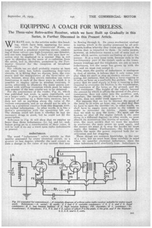
For the convenience of the reader, Fig. 21, which was published last week, is again reproduced, and
on a larger scale. It gives all the information. neces sary for connecting up a three-valve receiver, hut it does not tell us anything about the value of the various components, and so we should not be able to make up a practical receiver from this diagram without further information. In other words, it is like a doctor's prescription with the quantities left out. The chemist could tell from it whether he had the necessary drugs in stock, but he could not fill the prescription.
Reference to Fig. 21 will show that we employ no fewer than three inductances—Li, L2, and Lg—and, before going on to a consideration of their value, it will be well if we say a-word upon radio inducdtances in general.
Inductances.
The word " inductance " refers strictly to that quality possessed by every electrical circuit, to a greater or less degree, whereby the said circuit resists a change in the value of any current: that may
be flowing through it. Its exact mechanical analogy is inertia, which is the quality possessed by all ponderable.bodies whereby they resist any change in the. motion that is imparted to them. In radia jargon, however, an inductance means a coil of some sort or other which carries currents oscillating at radio fre,. quency. It is a very loose term, because coils in the low-frequency part of the circuit, such as the transformer windings and the telephones, are just as much inductances, but the usage has grown up with the art, and we must just accept it.
Now, since the quality of inductance is analogous to that of inertia, it follows that it only comes into play when we start or stop an electric current.Supposing, for instance, that we have a lorry running at 10 miles an hour on a perfectly flat surface., The only power that we need supply to keep it running is that required to ove.reome the friction in the transmission, the resistance of the tyres on the ground, and the wind resistance. The weight of the vehicle„ beyond the amount by which it affects the second of the above resistances, noes not enter into the question; and, therefore, the inertia, which is a function of the weight, does not make itself apparent
But suppose that we try to inerease the speed of the lorry to 15 miles an hour, say, we shall find that we have to open the throttle—or, in other words, we shall have to supply more power to the vehicle in order to overcome its inertia. Again, suppose that we wish to stop the lorry. We must use the brakes, or shut off the engine (which is the same thing in a different degree); in other words, we must absorb its momentum (the inertia of motion), Moreover, the more quickly that we want the machine to accelerate, the more power we must apply, and the sooner we want it to stop the harder we must apply the brakes. Furthermore, the heavier the vehicle the more the power required both for acceleration and for stopping. These thing i are common knowledge, in the case of a lorry, but we must bear them carefully in mind when we consider electrical inductance, since the same inferences hold absolutely true. Inductance in a circuit has no effect so far as steady current is concerned. It only makes itself felt when a current is started, stopped, or reversed, which is a combination of stopping and starting. It therefore affects all alternating currents, and, from our lorry, analogy, the faster the rate of alternation the greater_ the effect of a given amount of inductance. In dealing with slow-speed alternating currents— such as those used for commercial power supply, of telephone currents. etc.—an inductance, to be effeetive, must consist of many turns of wire on an iron core. When, however, we come to the very high frequency oscillatory currents used in radio transmission, the inductance of a few turns of wire alone is sufficient to give noticeable effect, and the presence of an iron core is not only unnecessary, but is actually harmful, since it raises the inductive value of any coil to a figure far beyond that which is useful for our purpose.
It follows, therefore, that radio inductances are coils of wire wound without iron or other magnetic material, and in the next article we will begin to discuss the various forms that are taken by these in practice.